An Overview on Surfaces
This article describes the main characteristics of think3 surfaces.
Specialized surfaces and NURBS
think3 surface entities can be divided into specialized surfaces, namely:
- Planes
- Circular cylinders
- Tabulated cylinders
- Ruled surfaces
- Surfaces of revolution
- Coons surfaces
- Proportional surfaces
- Fillet surfaces
and NURBS. Entities of the latter type are used to describe all other types of surfaces, namely:
- stretched surfaces (provided they are not defined as Coons surfaces)
- Spined surfaces
- Fitted surfaces, interpolated surfaces, etc.
Each surface has a parametric representation, that is to say, it is expressed as a function of the two parameters u and v which vary within the range [0,1]. The mathematical equations which describe the three coordinates of each point on the surface are equations with degree nu in variable u and degree nv in variable v and are called the "parametric equations" of the surface.
Characteristics of NURBS surfaces
The considerations made in connection with curves also apply to each of the two surface parameters, considered separately, in regard to the following:
- arcs and joints
- degree
- continuity.
As with curves, increasing the degree also increases the flexibility of a surface, although the latter becomes less smooth.
Continuity therefore also applies to both position and slope (tangency). In this case the concept of continuity is extended to entire arcs or edges separating different surfaces, which must therefore be considered as the loci of points with positional, slope or curvature continuity. See further details on continuity in the Continuity Types document.
Each portion of a NURBS surface "controlled" by a single set of control points is called a "patch" of that surface:
Control points
Each NURBS surface, like a NURBS curve, has a set of control points which control its shape but which do not necessarily lie on the surface.
The concepts describing NURBS curves can be extended to a NURBS surface if applied to the isoparametric curves of the surface.
The broken line joining the control points of a curve is called the control point polyline or polygon or defining polyline.
A numeric value, called the weight, is associated with each control point. Initially, the value of the weight is 1, but you may change it at any time. If you increase the weight of a control point, the curve moves closer to the control point, if you reduce it, the curve moves away from it. If you move the control points, the shape of the curve changes accordingly.
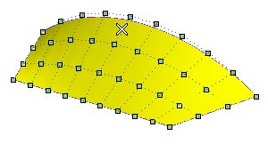
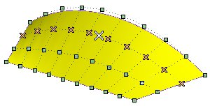
A square filled marker (the color of the filling depends on your color set, though default is green) is used to display control points when they can be selected like, for example, in the Surface through Control Points command.
On the contrary, an empty square marker is used to display control points that cannot be selected, like for example, in the preview of the Convert Surface to NURBS command.
Please note that a cross marker is used to highlight selected control points.
Selection
The method to be used for the selection of an entire "row" of control points is really simple. In fact, you just need to click on the one of the two dotted "lines" of the polygon mesh along the direction of which you want to select the points. You can proceed as follows:
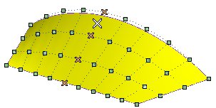
There are two lines of the polygon mesh intersecting just below the position of the cursor. If you click on any position along the line of the polygon mesh above or below the point:
all the "vertical" row of control points will be selected:
Similarly, if you click on any position along the line on the left or on the right of the point:
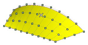
all the "horizontal" row will be selected.
Associative surfaces (Skins)
Associativity is a characteristic which can be assigned to a surface so that it will retain a link to the base entities it derives from. Associative surfaces are Skins, that is open solids. Therefore, if you modify the base entities of a skin, it will be modified accordingly; each skin has a history and is displayed in the Model Structure.
Managing old version files
Files created with older versions of think3 applications might contain old associative surface entities, which were different from the skins that are currently obtained as results of applying the commands in the associative mode.
Such files are correctly and thoroughly managed in the current version: they are loaded as they are and the application is capable of rebuilding and redefining them correctly. |
The Associative Mode check box, available in the selection list of many commands, enables you to create those associative entities called Skins, that is open solids, which retain a link to the surfaces/curves they derive from:
 |
| When the check box is selected, the resulting surface will be a skin. It will retain a link to the entities it derives from. A specific node displaying both the original entities and the resulting skin will be added to the Model Structure. |
 |
Selecting non-associative entities
If you select non-associative entities (such as non-associative surface borders or non-associative curves), a message will be displayed to warn you non-associative entities have been selected and that they will become the root of the structure. |
|
|
When the check box is cleared, the resulting surfaces will not be associative: they will retain no link to the entities they derive from. |
Associativity is available for the following surface creation commands.
Skins obtained using Break Solid
As to the associative surfaces you can obtain using the Break Solid command, which enables you to break a solid up into all its component surfaces (by using the
Global option) or extract only some of the component surfaces (by using the
Local option), the following has to be observed.
- In the case of Local break, you can select the
Associative Mode check box so that the surfaces you obtain are skins, thus linked to the original solid (if you modify the solid, the skins will be modified accordingly).
- If you use the Global option on a solid you had made using associative surfaces (see
Make Solid), you will still obtain skins.
|
Associativity is also available for the following surface editing commands.
Editing a skin in non-associative mode
In case you apply an editing command to skins, the Associative Mode box in the selection list will automatically be checked in the selection list. If you decide to apply the command in non-associative mode, that is to uncheck the
Associative Mode box, a warning will be displayed so as to inform you that the command cannot be applied in such a way to the selected skins but only to non-associative copies of the surfaces automatically created by the application. |
Associativity can be removed from a surface by using the
Unlink Solid command.
The selected surface will be converted to a surface with its own history in the Model Structure (such an entity is also ordinarily known as a History Graph Genitor), while all of its former associativity links to the parent entities will be removed.
Finally, take into account associativity can be applied or removed from entities using the
Enable Associativity and
Disable Associativity commands respectively.
| Managing the modification extension to dependant entities (children)
Entities can have children, which means entities created in relation with them and thus depending from them. Obviously, a modification performed through one of the above listed editing commands applied to the parent entity can affect the children as well. Thus, a specific option — Update Dependencies — is displayed only if at least one of the selected entities has children, so as to enable you to decide whether to extend the modification also to the children or not.
If Associative Mode is selected:
- When the Update Dependencies box is cleared, the modification is not applied to the children (default).
- When the Update Dependencies box is checked the modification is applied also to the children (after updating the model through
Rebuild Model).
If Associative Mode is cleared there are two cases:
- If the entity is not a History Graph Genitor (that is a generic root skin, displayed in the model structure through a generic Skin icon
 ), the
Update Dependencies check box is not available. ), the
Update Dependencies check box is not available.
- If the entity is a History Graph Genitor, the Update Dependencies check box is available and its behavior is the following:
- When the Update Dependencies box is checked the modification is applied to the selected entity and to the children (after updating the model through
Rebuild Model).
- When the Update Dependencies box is cleared, the modification is applied to a copy of the selected entity and not applied to the children.
|
In the following example some associative isoparametric curves of a surface have been used to create skins. Then the Trim/Extend Surface command — with the
Associative Mode box checked — has been applied to the surface and one of the parameters has been reduced to half of its original value.
- If Update Dependencies is cleared, the modification is not applied to the skins:
- If Update Dependencies is checked, on the contrary, the modification is applied to the skins (after running
Rebuild Model).
In the same model, if you uncheck the Associative Mode box:
- If Update Dependencies is cleared, the modification is applied to a copy of the selected entities — a specific confirmation request is issued — and the skins are not updated.
- If Update Dependencies is checked, the modification is actually applied to the selected entity and to the skins as well.
Managing multi-face skins
If the editing command is started in non-associative mode (that is, the Associative Mode box is cleared), the selection of multiple internal faces of solids is enabled. The command will be performed on copies of the selected faces.
In case the editing command is started in associative mode (that is, the Associative Mode box is checked), the selection of multiple internal faces of solids will be enabled only in those cases for which it makes sense, that is namely for the following commands:
In this case, the modification will be applied to the actually selected faces, rather than to copies. |
Redefinition of modifications applied to surfaces
When you apply the command to entities formerly modified using the surface editing commands, take into account the following:
- Entities can be added or removed from the ones the modification is applied to, but no replacement is allowed.
- The Update Dependencies option cannot be redefined.
 e-Learning on Base Surface Modeling
e-Learning on Advanced Surface Modeling