The process of animating a model is composed of multiple individual activities. If we consider the animation to be a complete wall, the individual activities form its bricks. There is no specific position of the bricks in the wall. However, it is necessary to keep in mind that the wall has to be constructed bottom-up. The illustration given below demonstrates the procedure to animate a Robotic Arm. Follow the links in this document to understand the individual activities that are involved in creating the animation.
| 1. |
Start the command from the
menu; the
Animation dialog box is displayed. By default, this dialog box is docked at the bottom of the Graphics Area. To make it a floating one, drag the control bars of the dialog box, which are displayed on its left, and drop it on to the Graphics Area.
|
| 2. |
The List of Animations is initially empty. Create a new animation with the name Animation 1 by referring to the document Managing the Animation List. Only after the first animation is created the buttons in the
Animation dialog box become active.

|
| 3. |
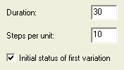
Make the settings for the animation as per the following figure by referring the to Animation settings document.

|
| 4. |
Adjust the display of the graphical area by using the view control buttons such that the complete animation scale is visible in it. Refer to the Graphical Area View Controls document to execute this step.

|
| 5. |
Add the ExtAng variable as the first evolution by referring to the Adding Evolution for Animation document.

|
| 6. |
Rename the ExtAng variable as Extender_Ang by referring to the Managing the Evolutions document.
|
| 7. |
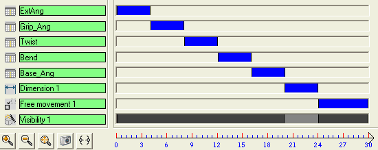
Create the first variation by referring to the Creating Variations document. Its parameters will be:
Start time = 0,
End time = 4,
Start value = 65,
End value = 40
|
| 8. |
Repeat step 6 and 7 to create evolutions and variations for other variables as per the following data.
- Variable = Grip_Ang,
Start time = 4,
End time = 8,
Start value = -50,
End value = -10
- Variable = Twist,
Start time = 8,
End time = 12,
Start value = 0,
End value = 270
- Variable = Bend,
Start time = 12,
End time = 16,
Start value = 30,
End value = 0
- Variable = Base_Ang,
Start time = 16,
End time = 20,
Start value = -45,
End value = 90
|
| 9. |
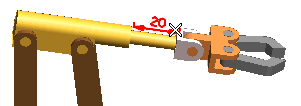
Refer to the Adding Evolution for Animation document and add the next evolution as Dimension by selecting the length as shown in the following figure.

Set its variation parameters as:
Start time = 20,
End time = 24,
Start value = 20,
End value = 40
|
| 10. |
Add the next evolution as Free movement of the Base (Base) by rotating it 90 degree in clockwise direction. Refer to the Adding Evolution for Animation and Creating Variations documents to execute this step. Set its variation parameters as:
Start time = 24,
End time = 30,
|
| 11. |
Add the Visibility evolution to Link1 and Link3 (Link1 and Link3) by referring the Adding Evolution for Animation and Creating Variations documents. Set its variation parameters as:
1st variation - Start time = 0,
End time = 20
2nd variation - Start time = 24,
End time = 30
|
| 12. |
All the evolutions needed for the animation have been created. You can create more evolutions if need be. The graphical area will appear as shown in the following figure.

|
| 13. |
Now play the animation by referring to the Animation Playback document.
|
| 14. |
Save the animation in an AVI file by referring to the Creating an AVI document.
|
| 15. |
The created animation can also be used to check for collision between the components during their movement. Refer to the Collision Detection document to learn more.
|


