Creating a Hole on a Cylindrical Surface
To create a hole on the cylindrical surface of the solid you need to create a cylinder of size 35(diameter)*75(height). Follow the steps given below to create a simple hole on cylindrical face of a solid having an axial symmetry (for example, a cylindrical or conical face).
- Start the command and ensure the For screw check box is cleared.
- Next, select the cylindrical face on which the hole is to be created.
- The Type drop-down list is automatically set to Cylindrical option, if not make the change. The origin is placed by default on either of the side faces (top or bottom). To move the origin to the other face, right-click on the Reference to origin selector and choose Reset.
- The reference direction (from which the hole direction is measured) can be defined in three different ways. This can be done by using one of the options available in the Radial direction drop-down list.
- 2 points - The reference direction will be in the same direction as the one obtained by joining the two selected points by a straight line.
- Line - The reference direction will be in the same direction as that of the selected line.
- End point - The reference direction will be in the same direction as the one defined by joining the selected point with the origin by a straight line.
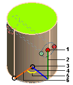
- The various parameters that will define the location of the hole on the cylindrical face are shown below.
 |
- Point at which the hole (axis) will be created
- Height of the hole from origin
- Origin
- Direction of the hole
- Angle (between the hole direction and the reference direction)
- Reference direction
|
The point for the hole creation is specified using the Cylindrical Coordinate ( ) system.
- Next, you need to enter values in the displayed mini-dialog boxes to create hole. Enter 15 in the Diameter mini-dialog box and to specify the height of the hole (axis) from the origin enter 25 in the Distance mini-dialog box.
- Next, to specify the direction of the hole with respect to the reference direction enter 45 in the Angle mini-dialog box.
-
Note
The default option is End point and the point that is initially selected for this option is the one on which you clicked to select the cylindrical surface. |
- Click
 or
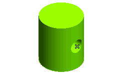
or  to confirm your selections and create the simple blind hole, as shown in the image below. Click
  to discard your changes.

Note
The above mentioned steps can also be followed for creating shaped hole and shaft on axially symmetric faces. |
Also try to...
Tips and Tricks

 ) system.
 or
or  to confirm your selections and create the simple blind hole, as shown in the image below. Click
  to discard your changes.