Inserting Tubing Parts
The following illustration explains how to insert various tubing parts by using the Insert Tubing Part command. Open the Tubing_parts.e3 file available in the Samples folder of your think3 installation and follow the steps given below.
- On opening the file you will see the 3D Profile over which you are going to insert the tubing elements. Start the Insert Tubing Part command.
- In the Type drop-down list you need choose the element that you want to insert in the network. In the tutorial we start by selecting Elbow.
- Each element can be inserted only over a specified anchor, click here for details. Select the corner as shown below for the Anchor.
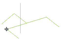
- Ensure that Steel - mean pressure - welded joint is selected in the Line drop-down list. This selection will remain the same for other elements too as we want to insert tubing elements only of the welded type.
- Expand the Line node (
 ) to view the Elbow - Curve option and select 90º long radius from the drop-down list.
- Now expand the node (
 ) for the Elbow - Curve option; the corresponding catalog is displayed in a separate dialog box. Double-click over 1" in the Size(") column.
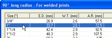
Note that you have to perform this step also for all other elements so as to select the same size in their corresponding catalogs to ensure that there is no mismatch in size of the elements being inserted on the network.
- The preview of the Elbow will be displayed over the path. Select Apply (
 ) to create it.
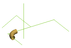
Note that the command is still active and you can continue inserting more tubing elements.
- Retracing the previous steps, insert another Elbow in the opposite corner.
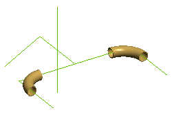
- In the Type drop-down list choose Cross and select the anchor as shown below.
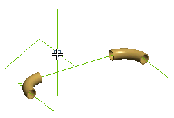
- Ensure that Cross is selected for the Connector option. Select a 1" Cross from the catalog and insert it in the network.
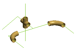
- In the Type drop-down list choose Tee and select the anchor as shown below.
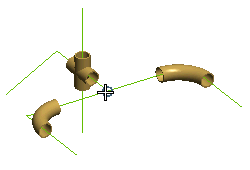
- Ensure that Tee is selected for the Connector option. Select a 1" Tee from the catalog and insert it in the network.
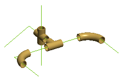
- In the Type drop-down list choose Socket and select the anchor as shown below.
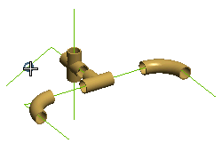
In the preview of the Socket, red arrows are displayed that can be selected to rotate it. You need to ensure that the larger end of the Socket is facing towards to Cross.
- Ensure that Reducing Bush is selected for the Connector option. Select a 1" Reducing Socket from the catalog and insert it in the network.
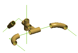
- In the Type drop-down list choose Elbow and select the anchor as shown below.
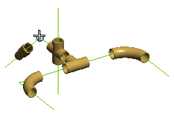
- Ensure that 45º short radius is selected for the Elbow - Curve option. Select a 1" Elbow from the catalog and insert it in the network.
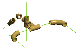
- In the Type drop-down list choose Tube and select the anchor as shown below.
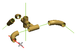
- Ensure that for welded joints is selected for the Tube option. Select a 1" Tube from the catalog and insert it in the network.
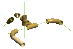
- Repeat the above two steps to inset Tube over all other line segments except the one that is towards the smaller end of the Socket.
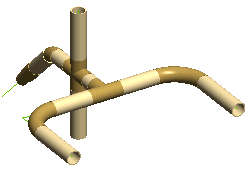
- For the last line segment you need to insert the tube after selecting a size 3/4" from the Tube catalog so as to it is compatible with smaller end of the socket.
- Finally you will insert a Flange. In the Type drop-down list choose Flange and select the anchor as shown below.
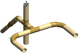
- Ensure that Collar is selected for the Flange option. Select a 1" Collar from the catalog and insert it in the network.
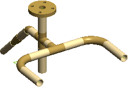
- You can Cancel (
 ) the command once all the elements have been inserted. Later on you can use the Modify Tubing Part command to edit any of the inserted tubing elements.
Also try to...

 ) to view the Elbow - Curve option and select 90º long radius from the drop-down list.
 ) for the Elbow - Curve option; the corresponding catalog is displayed in a separate dialog box. Double-click over 1" in the Size(") column.
 ) to create it.


 ) the command once all the elements have been inserted. Later on you can use the Modify Tubing Part command to edit any of the inserted tubing elements.