An Overview of Tubing
ThinkDesign provides you the tubing functionality that supports the creation of Pipe Works. The process of Tubing involves covering a predefined path (called the Network) with Tubing elements (like tubes, elbows, flanges, connectors, etc) stored in the thinkparts catalogs. The creation of tubing can be done automatically covering in one shot the whole path, or by filling the path by making insertions piece by piece. All tubing elements can be chosen from a specific library. The user is provided with a standard library containing the frequently used tubing elements. Also, specific and custom-made objects can be added to the library. The Tubing functionality demands the following workflow:
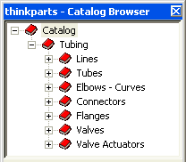
All the Tubing elements are saved in the thinkparts Tubing catalogs. To view the Tubing catalogs, choose Tools thinkparts
 Manager command from the menu bar; the thinkparts - Catalog Browser window is displayed, as shown in the image below.
In case the Tubing catalog is not present, you need to
Import it. Otherwise, on starting a
command, a warning will be displayed instructing you to import the catalog.
thinkparts provides the user with a library of tubing elements. All tubing elements can be chosen from a specific catalog, which is a library that includes both geometric values and specific attributes for each tubing element. The user can update the tubing library with custom made tubing catalogs.
Note
The Lines index contains the Line Specification, and not tubing elements. The Line Specification acts as an interface between the library and the Tubing commands. Each Line Specification is related to a specific catalog containing predefined tubing element catalogs associated to it. When the user selects one of the Line Specifications (during the Tubing command's application), only the tubing elements associated to it are applied along the tubing path. For example, a Line Specification can be for welded joints or threaded connectors. Hence on selecting one of them will insert only the corresponding type of elements in the network. |
The tubing path is defined by a profile made only of straight line entities. You can make use of either a 2D or 3D profile to define the tubing path. In case you select a non-linear profile as the tubing path, the command is applied only along straight lines, and also a warning is displayed informing you that the selected path is not completely covered by tubing elements.
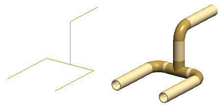
The program analyzes the tubing path and applies the appropriate tubing elements along it to form the complete tubing network. You can also define independently each tubing element to be placed along the tubing path. The following image shows a typical example of tubing path and the resulting tubing network.
You create the tubing network by inserting the tubing elements along the predefined path. You can carry out this process in the automatic covering or single element insertion mode.
The Tubing Network command enables you to perform automatic covering. Once you select the network path and define the Line Specification, the program adds all relevant elements to complete the tubing network. Using this command only the standard tubing elements are added to the network.
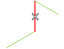
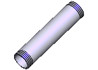
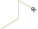
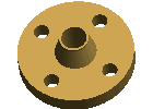
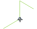
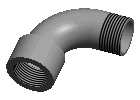
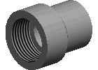
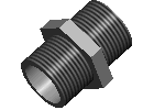
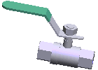
The Insert Tubing Part command enables you to insert one part at a time along the tubing path to complete the network. Using this command, you can also add non standard tubing elements like Valves, Pressure gauges, etc to the network. Each type of tubing element can be inserted only at a specific location on a network defined by the anchor; the following table provides the details:
| Element |
Anchor |
Inserted Component |
| Tube |
Line element |
 |
| Flange |
Endpoint |
 |
| Elbow |
Corner |
 |
| Tee |
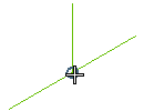
Perpendicular line |
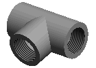 |
| Cross |
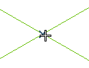
Crossover line intersection |
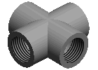 |
| Socket |
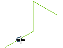
Meeting point of two collinear lines |
 |
| Nipple |
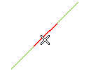
Untrimmed line segment of the nipple length |
 |
Other Parts
(Valves) |

Meeting point of two collinear lines |
 |
Note
Each component inserted along the tubing path to form the network is displayed in the Model Structure. However, it is not possible to apply the standard assembly component modification commands on Tubing components. These include ,
Break Component,
Unlink Component etc. If tried, a suitable warning is displayed informing you that these operations are not allowed on standard parts. |
While executing the tubing commands, you need to specify the Line Specification. It defines the way to group all tubing elements requested for a specific covering type. This can be done by using the Line drop-down list. By default, two Line Specifications are present in the library: Steel - mean pressure - welded joints and Steel - mean pressure - threaded connectors and you can make a selection between them. As per the selection made, all the tubing elements applied along the tubing path will only be of the corresponding type.
As per the selected Line specification, the different tube element options associated to it are displayed in the selection list. By clicking the node symbol ( ), the corresponding catalog with all its data is displayed in the form of a dialog box. From this catalog, you can make the selection (by double-clicking) of the tubing element with the required configuration. Now, the program automatically chooses all other necessary tubing elements for the network, such that consistency is maintained among all of them.
In case you are using the Line Specification for Welded Joints, it is possible to insert the Flanged Elements. To do so, select the Flanged check-box. The selection list will display the Flange node; use it to select the flange configuration from the corresponding catalog.
All the tubing elements are managed by thinkparts. Hence, the modification or creation of new tubing elements has to be done by updating the Tubing catalogs. To do so, use the
Catalog Manager. Using the Catalog Manager commands you are enabled to customize your library by creating new indexes, new catalogs and modifying the dimensions of the existing tubing elements.
You can also create and customize the Line specification. When you do so, you have to ensure that there are corresponding tubing elements available in the catalog for the new Line Specification.
Related topics ...
 thinkparts
 Manager command from the menu bar; the thinkparts - Catalog Browser window is displayed, as shown in the image below.


 ), the corresponding catalog with all its data is displayed in the form of a dialog box. From this catalog, you can make the selection (by double-clicking) of the tubing element with the required configuration. Now, the program automatically chooses all other necessary tubing elements for the network, such that consistency is maintained among all of them.