Before you start creating your custom tubing catalogs, you should become familiar with the following rules and conventions that apply to the customization of Tubing.
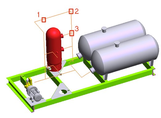
In order to create a pipe, you have to create the pipe path (or network) by drawing a chain of segments that may cross. Then you cover the path with Tubing parts that the program finds in the catalog of Tubing components and that it sizes according to the Nominal Pipe Size (NPS) or Diameter Nominal (DN) dimension that you require. Here is an example of pipe path:
The following is the definition of some of the terms used in Tubing:
| Path | Any 2D or 3D polyline that connects two or more points. In ThinkDesign the path is a 2D or 3D profile. The path is composed of:
|
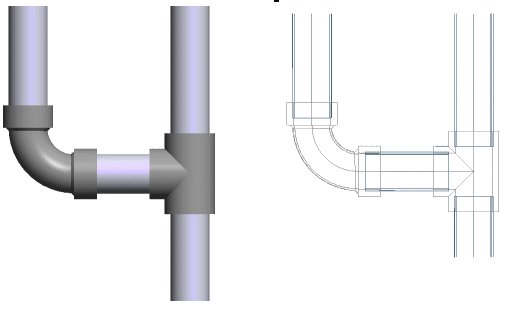
| Fittings | These Tubing components include Tubes (1), Flanges, Elbows (2), Tees (3), Crosses, Sockets, Nipples. The program is able to select and orient these components automatically based on the shape of the Tubing path. |
| Other parts | All Tubing components such as Valves, Pressure gauges, Degasifiers, etc. that are not Fittings and require additional user input to cover the Tubing path correctly. |
| Covering the path | The action of covering the Tubing path with the fittings consists of two basic steps:
|
A thinkparts library of samples of these components is provided with the software. The library is initialized the first time you start one of the Tubing commands. You are also enabled to create you own catalogs of custom parts and add custom parts to the existing catalogs.
The process of covering a Tubing Path requires the following to be available:
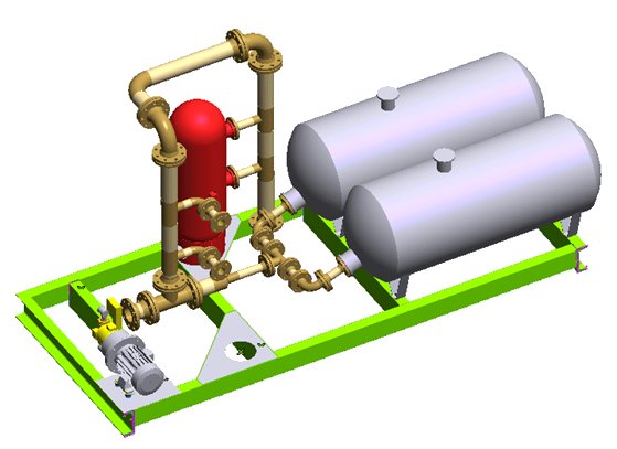
When you assign the nominal diameter to the Tubing required to cover a path, and the program finds all components that fit the requirements, the Tubing path can be covered:
A Line Catalog is an ordered list of components that can be assembled to form the tubing line. One or more Line Catalogs may be defined according to the type of fluid to be transported, the fluid temperature and the fluid pressure.
For example, a galvanized iron service line (for water, compressed air, etc.), could be composed of:
Sample Line catalogs are installed by the program the first time you use one of the Tubing commands, and you are enabled to manage them with the thinkparts Catalog Manager command:
In order to create your own Line catalogs, you can edit a copy (see Copy Catalog) of an existing one, paying attention to not remove or add columns.
Each row in the Line catalog follows the rules in the table below. The Edit Values command enables you to edit the catalog.
| Row header | Description | ||||||||||||||||||||||||||||||
| Part | The generic short name of the part. The program displays this datum when the user has to choose the element type. | ||||||||||||||||||||||||||||||
| Catalog | A short description of the part category. The program displays this datum when the user has to choose the element type. | ||||||||||||||||||||||||||||||
| Catalog ID | The name of the catalog that contains the 3D model of the part. You find this information in the Catalog code: field of the catalog properties | ||||||||||||||||||||||||||||||
| A.ID | The Application IDentifies indicates to the program the type of part master model. The allowed values are:
|
||||||||||||||||||||||||||||||
| Insert | A flag with the following values:
|
||||||||||||||||||||||||||||||
| Representation | The name of the part representation class. You find this information in the Name: field in the Class attributes area of the Representations command wizard. | ||||||||||||||||||||||||||||||
| Size (") | The name of the field that contains the NPS or DN value of the part. You find this information in the List of fields table of the Edit command when applied to a catalog. | ||||||||||||||||||||||||||||||
| Red. Size (") | The name of the field that contains the reduced diameter of the part, if any. You find this information in the List of fields table of the Edit command when applied to a catalog. Enter None when not used. | ||||||||||||||||||||||||||||||
| Length (mm) | The name of the field that controls the part length. This value is mandatory and must be set to TD_LENGTH when A.ID is set to 0 (Tube). You find this information in the List of fields table of the Edit command when applied to a catalog. Enter None when not used. | ||||||||||||||||||||||||||||||
| Curve | The name of the field that controls the angular value of the elbow, if applicable. This value is mandatory when A.ID is set to 2 (Elbows) and 3 (Tees at a different angle than 90° and Y's). You find this information in the List of fields table of the Edit command when applied to a catalog. Enter None when not used. | ||||||||||||||||||||||||||||||
| Origin | The name that you have assigned to the Symbolic Reference that identifies the part origin. | ||||||||||||||||||||||||||||||
| Input | The name that you have assigned to the Symbolic Reference that identifies the input flow. | ||||||||||||||||||||||||||||||
| Output | The name that you have assigned to the Symbolic Reference that identifies the output flow. | ||||||||||||||||||||||||||||||
| Secondary Output | The name that you have assigned to the Symbolic Reference that identifies the reduced diameter secondary output. Enter None when the secondary output is not present or matches the nominal diameter. |
Any parametric think3 3D model can be used as master model for a Tubing parts catalog, provided that:
When the above criteria are met, the program is able to position the elements of the line correctly, by connecting the outputs to the inputs of the following parts and propagating the diameter reduction along the path:
While building the Parts catalog, you should take care in defining the following parameters for the use with Tubing:
If you require ThinkDesign to insert automatically the Line axis in the layout, add to your customized parts a profile made of curves of type Reference to represent the part axis. Create the User Defined Property TD_CENTERLINE of type Integer and assign it to the profile with value=1. When you later add to the layout a view of the Tubing line, the program will display the axes, provided that the Profile references options is checked.