Sheet Metal workflow in think3
This document explains the workflow of the Sheet Metal module in think3.
 e-Learning Material: e-Learning Material:
A friendly set of e-Tutorial videos on Sheet Metal has been created and is available on the Customer Care Corporate site (e-Learning home page). Take a look at the list of the available educational videos on Sheet Metal here: e-Learning: Sheet Metal.
Enjoy your lessons! |
Basic philosophy
The final goal for a Sheet Metal user is to be able to design a manufacturable 3D part. In order to achieve this goal, he/she needs to "see" the part both in a flattened state (typically as a drawing to be sent to the shop floor) and as a 3D object (taking into account deformations caused by the bending process).
The fundamental idea behind think3's Sheet Metal philosophy is that the user is not forced to follow a single predefined approach. In fact, it is possible to start from scratch or to start from an existing, possibly imported, model as well. In any case the user can mix these two approaches and will take advantage of the set of specific features and of an enlarged and powerful library of Sheet Metal specific Smart Objects.
Sheet Metal Parameters
In order to be manufactured, a Sheet Metal part must satisfy a number of requirements that make the bending and forming process feasible.
In particular the characteristics of the material to be bent and of the manufacturing tools have to be specified (i.e: material thickness, bend allowance, bend radius, etc.)
The think3 application provides a set of global parameters (the Sheet Metal category of the
Entity Properties) that are automatically assigned to an object when the first Sheet Metal feature is created.
Because in the think3 application it is possible to create models containing multiple solids it is mandatory that each solid has its own set of Sheet Metal parameters. Therefore, a Sheet Metal Parameters page is accessible by right-clicking on the solid icon in the
Model Structure. The page is available only if the corresponding solid has at least one Sheet Metal specific feature.
Starting from scratch
The first step in designing a Sheet Metal part from scratch is usually one of the following two:
|
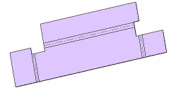
Sketch a closed profile (i.e: a rectangle) and extrude it. In this case the Thickness equals the extrusion depth. |
 |
|
|
|
|
Sketch an open profile (i.e: a L-shaped profile) and extrude it with thickness option on. In this case Thickness equals the extrusion thickness. The command is available to accomplish this task. |
 |
After the solid has been created using one of the two methods above, the user can add specific Sheet Metal features like and
.
is used to add side walls while
is used to explicitly add a bend to existing faces.
The user does not generally need to specify thickness when applying Sheet Metal features: the system determines it automatically. If this is not possible a warning is displayed but it’s anyway possible to go on with the command. In this case the user has to explicitly specify a thickness.
Inherited thickness
This is a fundamental concept: when applying Sheet Metal features, the program will infer Thickness from the solid to which features are applied (if possible). This means that in the Sheet Metal Parameters page the thickness field will be flagged as inherited and grayed out. |
Each Sheet Metal feature provides a set of parameters (bend radius, k-factor, etc.) representing a subset of all the existing Sheet Metal Parameters.
Each of the feature specific parameters can either be inherited from the solid or set locally (i.e: general bend radius for a solid could be 2, but for a given flange it could be set to 4, typically because of a different tool used to bend the flange).
If a Sheet Metal parameter for a solid is modified, all Sheet Metal features inheriting that parameter will be updated. The Sheet Metal parameters are available in a bend table, which can be managed by using the . The bend radius values available in the bend table can be directly accessed and used while creating a Sheet Metal feature.
Starting from an existing solid
Many times it’s not possible to know in advance which manufacturing process will be used to produce a given piece. Or simply the piece could have been already designed (i.e: by subcontractor). Being able to flatten a generic solid is then a fundamental capability.
There are two typical problems when dealing with an existing solid:
- Precision. Especially if imported from external systems, the solid could be poorly designed and have a non uniform thickness, "almost" parallel faces or "almost" cylindrical roundings
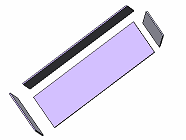
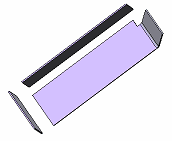
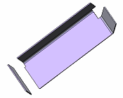
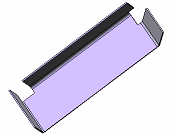
- How/where to open it. A typical solid cannot be flattened. There are not enough degrees of freedom. Take a shelled box. To flatten it the side faces should be "ripped" (open). This way they will detach from each other so that they can be flattened
Starting from version 8.0, think3 focuses on the second issue, the most common, while the first will be faced in future versions.
The assumption is that the starting solid has a constant thickness or, if this is not the case, that a shell feature is applicable to achieve it. This assumption does not apply for some features like slots, holes and fillets.
At this point the key feature to flatten the solid is a .
All the user has to do is just to select edges where the solid has to be "opened". (rip)
or sketch a profile that splits a face in two pieces ().
In both cases a little gap will also be created.
At this point the solid is ready to be unbent.
There are cases in which it is not possible to apply the same Sheet Metal parameters to all operations (for instance when different tools are used). In these cases it’s possible to explicitly create a feature assigning specific parameters.
Bend features can be applied to sharp edges and fillets.
There are cases in which it is not possible create a rolled Sheet Metal due to manufacturing constraints. In Such a situation the rolled portion of the sheet metal can be converted into a series of bends. These bends are called .
There are cases where separated solids needs to be joined to get single Sheet Metal Solid.
The feature enables to join the separated solids by adding a bend between them.
 |
 |
 |
| Initial Separated Solids |
After adding Union With Bend |
After adding another Union With Bend |
 |
 |
| After adding another Union With Bend |
Unbend final Solid |
Thick Sheet Metal Features
Features like slots, holes, chamfers and fillets on the Sheet Metal that defy the "uniform thickness rule" are defined as Thick Sheet Metal Features (TSMF). You can view the TSMF below:
Note
- Adding bends to existing fillets/sharp edges before adding TSMF (chamfers/slots/holes) is mandatory.
- None of TSMF should disturb the bend region except slots/chamfers along entire side face edge.
- Normal side face option may not work as expected in TSMF cases.
|
&
Whatever the approach used to build the part, sooner or later it will have to be flattened, thus providing a visual check on how the sheet metal will be cut, if there are any outstanding issues (for example: a wrongly shaped or too small/big relief) and, what is most important, enabling to add additional features while the model is flat (for example: a slot across a bend) to verify later what the result after the bending operation will be.
The feature enables to flatten the whole object of just a part of it (global unbend, local unbend). There is no need to add fillets or explicit bends (see below) in order to unbend an object. Models with sharp edges can immediately be unbent.
Sharp edges are unbent inheriting Sheet Metal parameters (relief type, k-factor, etc.) from the solid.
 |
 |
| Unbend flange |
Unbend rip (sharp edges) |
When an object is (globally or partially) unbent it is then possible to re-bend it. As it is the case when applying an unbend, the feature can be either global or local.
Rebend rip
Standard and specific SM features can be added while the model is flattened. For instance a hole can be cut across a flattened bend and then a rebend feature applied.
 |
 |
| Hole across bend |
Rebend |
Reliefs
Under certain conditions, bending operations can undesirably stretch or even break a piece of sheet metal. To avoid these problems, different kinds of reliefs are used. The think3 application enables the user to specify if and which kind of bend and corner relief must be applied.
Bend relief is typically used between two surfaces, typically with flanges, while corner relief is used when three or more faces meet at a vertex.
Reliefs are not individual features. They are "parameters" of Sheet Metal features like bend, flange, etc.
 |
 |
| Bend relief |
Corner relief |
Note that a corner relief like result can also be obtained using the feature:
Close corner
The role of Smart Objects
Smart Objects play a fundamental role in think3 Sheet Metal solution. They are used both to support forming operations and to extend basic Sheet Metal features, building new functionalities on top of standard features like flange or bend.
Sheet Metal Smart Objects inherit all relevant parameters (thickness, bend radius, etc…) from the object they are applied to.
Forming operations
In addition to being bent, Sheet Metal objects can also be stretched or formed using specific tools.
think3 provides the following forming Smart Objects:
 |
 |
 |
 |
 |
| Louver |
Dimple |
Cutout |
Bead |
Lance |
Extending standard Sheet Metal features
A number of useful Sheet Metal features are obtained as extension/specialization of the standard set available.
| Creating customized Sheet Metal Smart Objects
You are enabled to create your own customized Sheet Metal Smart Objects. The ones shipped with think3 are just examples. You can easily use them as "templates" to create your own ones. If you right-click on a Sheet Metal Smart Object in the
palette and select
, in the
Preview & Description tab you will find the model used to create the Smart Object. You can use the model both to see how the Smart Object was created and to create a new one by customizing it as you like.
|
Hem is a typical example (for details about all the available hems, see the description of the command). It is a flange with a fixed angle of 180°. It can be very useful, as it prevents you from having to redefine the 180° angle every time.
 |
 |
| Hem |
Tab flange |
Sheet Metal Smart Objects enabling you to perform the closure between two different pieces are also available.
Drawing Layout
To obtain a flat pattern drawing of the Sheet Metal part, the think3 application offers a new type of view: Flat Pattern View. This view creates a flattened drawing irrespectively of the model state (model could also be in bend state).
Sheet Metal drawings can optionally show bend lines and textual information associated to each bend line (angle, bend direction, etc.). See the
Drawing View-
Flat Pattern category page of
Entity Properties for further details).
Relief lines can optionally be removed from the drawing.
e-Learning on Sheet Metal