
Many improvements have been made in version 2019.1. This document contains a list of short descriptions for each new feature, improvement and enhancement.

The TDXchangeReader module is now capable to read:
ThinkDesign 2019.1.SP2:
ThinkDesign 2019.1 introduces some major changes for the Full Hybrid Modeling:
ThinkDesign have support for the Reverse Engineering activity with the Reshape and HQRE modules, including functionalities to manage meshes.
With previous releases, the user had been accessing Reshape commands from a separated Reshape drop-down menu in the menu bar.
Starting from ThinkDesign 2019.1, the Reshape commands, just like HQRE ones, are re-dispatched in respective places in menus , Insert|Modify ⇨ Curve|Surface|Mesh.
The activity toolbars Reshape and HQRE are still there.
Some commands have been moved to the standard menus File, Insert and Modify:
| Reshape command | Moved to | Note |
| Split Mesh with Plane | Modify ⇨ Mesh ⇨ Split with Plane | Enhanced |
| Split Mesh with Curve | Modify ⇨ Mesh ⇨ Split with Curves | Enhanced |
| Smooth Mesh | Modify ⇨ Mesh ⇨ Smooth | |
| Decimate Mesh | Modify ⇨ Mesh ⇨ Decimate | |
| Refine Mesh | Modify ⇨ Mesh ⇨ Refine | Enhanced |
| Sew Mesh | Modify ⇨ Mesh ⇨ Sew | |
| Remove Wrong Faces | Modify ⇨ Mesh ⇨ Remove Wrong Faces | |
| Fill Mesh Holes | Modify ⇨ Mesh ⇨ Fill Holes | |
| Curve on Mesh | Insert ⇨ Curve ⇨ Curve on Mesh | |
| Mesh Character Lines | Insert ⇨ Curve ⇨ Mesh Character Lines | |
| AutoPatching | Insert ⇨ Surface ⇨ Specialized ⇨ AutoPatching |
Some others are covered by existing or new commands:
| Reshape command | Covered by | Note |
| Import Mesh | File ⇨ Open... or Insert ⇨ From File... *.STL, *.PLY, *.OBJ,... | Enhanced |
| Export Mesh | File ⇨ Save or File ⇨ Save As... *.STL, *.PLY, *.OBJ,... | Enhanced |
| Cut Mesh |
Modify ⇨ Mesh ⇨ Remove Facets (option Split removed) Insert ⇨ Mesh ⇨ Separate (for the option Split) |
Modified New |
| Heal Mesh Normals |
Modify ⇨ Mesh ⇨ Repair (to fix orientation issues) Modify ⇨ Mesh ⇨ Invert (to invert the normals) Tools ⇨ Info ⇨ Analysis ⇨ Normals (to visualize the normals) |
New |
| Mesh Boundaries | Insert ⇨ Curve ⇨ Boundaries | Enhanced |
| Plane on Mesh | Insert ⇨ Surface ⇨ Specialized ⇨ Primitive on Mesh |
Others commands have also been re-dispatched:
| Compensator command | Moved to | Note |
| Offset Mesh | Insert ⇨ Mesh ⇨ Offset |
| File ⇨ 3D Printing ⇨ Create Mesh command | Moved to | Note |
| Create Mesh | Insert ⇨ Mesh ⇨ From Solid |
Separate mesh command (Insert ⇨ Mesh ⇨ Separate)
This command enables the user to separate a triangular mesh in different parts, by selection or by disconnected shells.
In the Mode drop-down list, choose the way the mesh will be separated:
The command can assign automatically a different layer and color for each created Mesh part. In the Layer increment and Color increment boxes under More Options, you can specify the increase in layer and color between a part and the next (the layer is the one displayed in the Layers tab; the color number is the one displayed in the color palette: see also " Setting and Modifying the Color").
| Initial mesh | Separated meshes |
 |
 |
Join Mesh command (Insert ⇨ Mesh ⇨ Join)
This command enables the user to join several triangular meshes to create a single mesh.
If selected meshes are disjoint, the resulting mesh will be multishell. Nodes closer than the specified Merge tolerance value are merged together.
Offset Mesh command (Insert ⇨ Mesh ⇨ Offset)
The command has been moved from Modify ⇨ Compensator to Insert ⇨ Mesh menu.
The functionality remains unchanged.
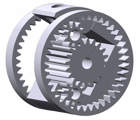
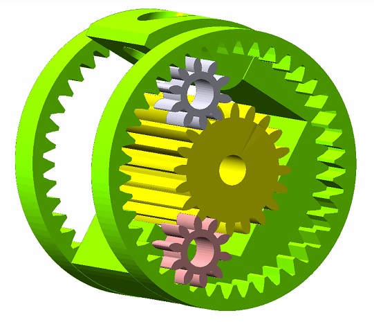
Mesh From Solid command (Insert ⇨ Mesh ⇨ From Solid)
This command enables the user to convert solids to meshes.
It replaces the mode Create Mesh moved from 3D Printing command.
Invert Mesh command (Modify ⇨ Mesh ⇨ Invert)
This command enables the user to invert the normals to the facets of a triangular mesh.
In the Invert Normals drop-down list, choose the way the mesh will be inverted: Manually, By direction, By axis or By point.
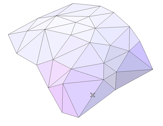
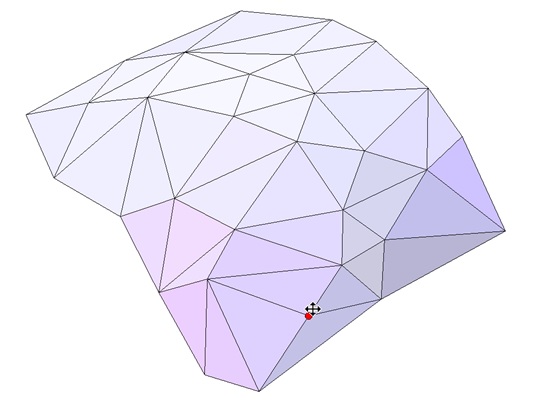
Split Edges command (Modify ⇨ Mesh ⇨ Split Edges)
This command enables the user to split the edges of a triangular mesh. The original edge will be cut. The inserted node is connected to the opposite nodes in the adjacent triangles.
It is useful for improving local mesh quality.
| Pick the edge to split | Drag the handle to move cut location |
 |
 |
Swap Edges command (Modify ⇨ Mesh ⇨ Swap Edges)
This command enables the user to swap the edges of a triangular mesh. The original edge will be replaced by an edge that connects the other two corners of the adjacent triangles.
It is useful for improving local mesh quality.
| Pick the edge to swap | Swapped edge |
 |
 |
Stanford Polygon Format (PLY) loading and saving
The PLY format, also known as the Stanford PoLYgon Format, is commonly used to exchange meshes.
ThinkDesign 2019.1 enables reading and writing files in the PLY format using respectively Open/Insert ⇨ From File... and Save/Save As....
Unit of measurement for loading STL, OBJ, PLY
The file formats STL, OBJ, PLY do not describe a unit of measurement in their specification.
In ThinkDesign 2019.1, on Load option pages for the aforementioned formats, the user can select the unit that he wishes to interpret the imported data from the Units of measurement drop-down list.
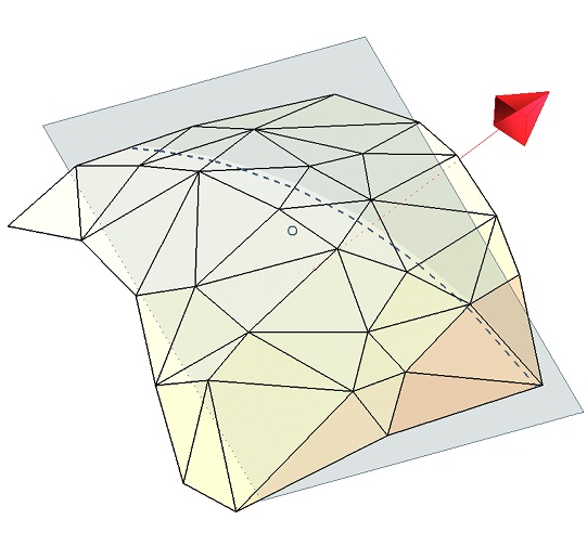
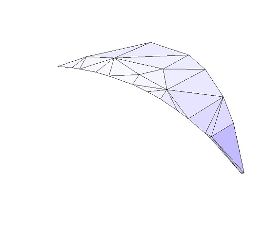
Split Mesh with Plane command (Modify ⇨ Mesh ⇨ Split with Plane)
Like some other commands dealing with meshes, this command has evolved for better performances and usability.
The user interface changes slightly:
| Initial mesh, limiting plane | Same mesh after splitting |
 |
 |
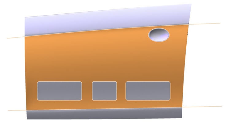
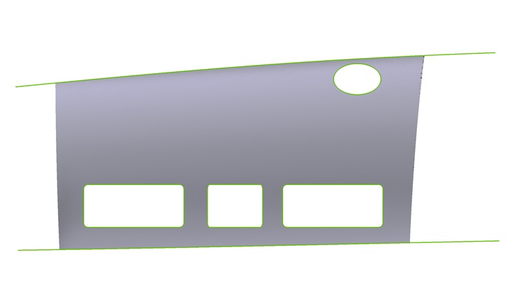
Split Mesh with Curves command (Modify ⇨ Mesh ⇨ Split with Curves)
This command has been greatly enhanced:
| Initial mesh, limiting curves and region to keep | Same mesh after splitting |
 |
 |
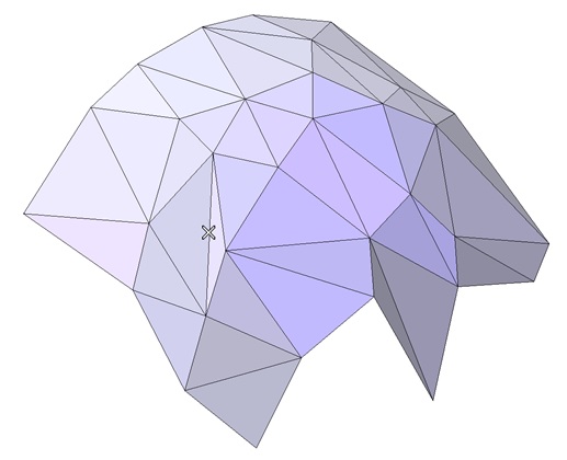
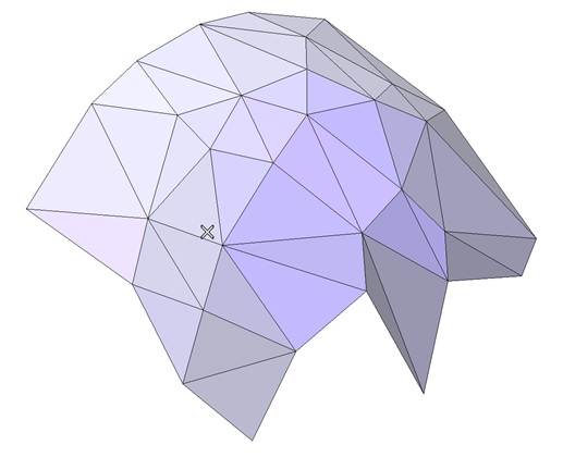
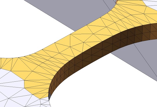
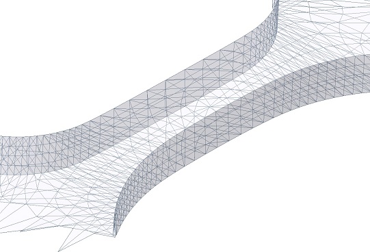
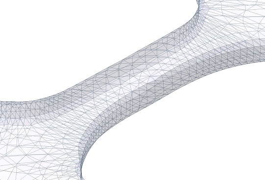
Refine Mesh command (Modify ⇨ Mesh ⇨ Refine)
The improvements impact:
| Mesh zone to refine | Crease detection = 150° | Crease detection = 10° |
 |
 |
 |
Analysis Normals command (Tools ⇨ Info ⇨ Analysis ⇨ Normals)
Previously, when the selected shape was a mesh, the command displayed the normals to the facets. Now, a new drop-down list has been introduced to display the normals either To Facets or To Nodes.
Boundary Curve command (Insert ⇨ Curve ⇨ Boundaries)
Starting from ThinkDesign 2019.1, it is possible to create the boundary curves of triangular meshes. The resulting curves are polylines (degree 1 NURBS).
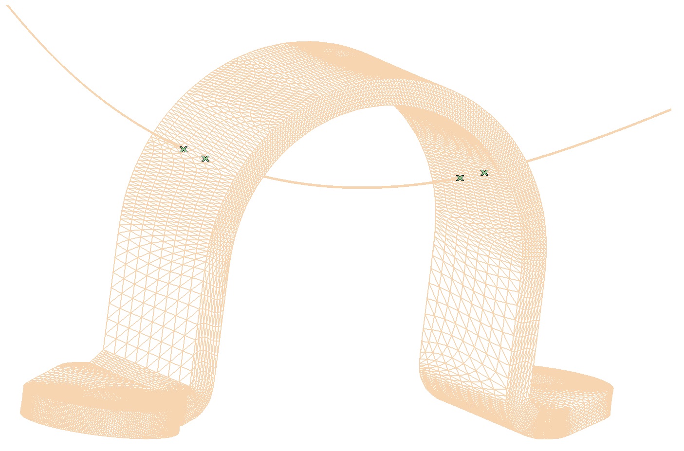
Point on Intersection of Curves/Surface/Mesh command (Insert ⇨ Point ⇨ On Intersection of Curves/Surface/Mesh)
Starting from ThinkDesign 2019.1, the command Point on Intersection of Curves/Surface, now labelled Point on Intersection of Curves/Surface/Mesh, enables you to select a mesh in the Surface/Mesh selector and to compute intersection points between the curves and the mesh.
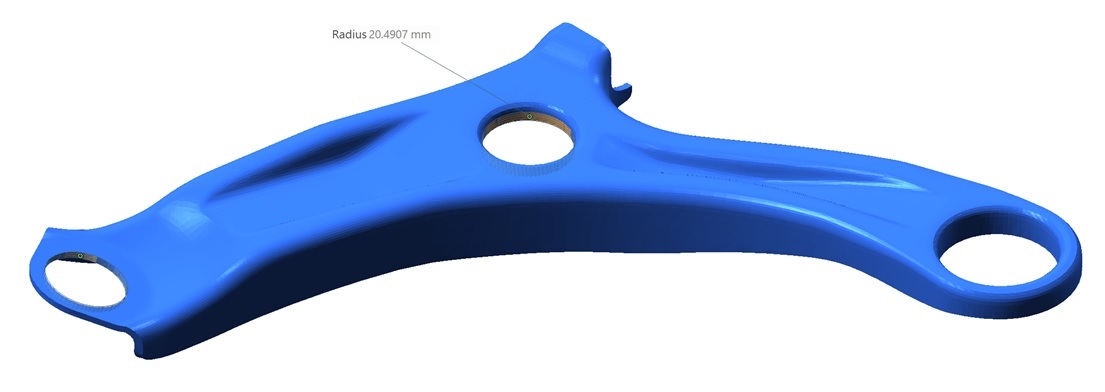
Primitive on Mesh command (Insert ⇨ Surface ⇨ Specialized ⇨ Primitive on Mesh)
The command shows the optimum value of the cylinder radius when it is not constrained. This can be very useful to better control the shape to build.
Convert solid to sheet metal, Fixed face definition (Insert ⇨ Sheet Metal ⇨ Convert solid to sheet metal)
While converting a solid to sheet metal, the command now allows to select a fixed face, otherwise defined automatically. This fixed face is the one on which the Flat Pattern View should be created.
Organize Formats (Format ⇨ Organize ⇨ Formats)
Material attribute can be now managed in General category like Layer or Color attributes.
The source code has been accurately revised to highly improve the program's robustness and reliability.


|
|