General Improvements
Version 2008.1 introduces the following general utility improvements.
Starting from this version it is possible to a have larger working area (Graphics Area) as the Parameter Area is removed from the toolbar space for the following list of commands:

New Organize submenu
The new Organize submenu has been added to the Format menu in order to increase the usability. All the existing organize commands (Organize Styles, Organize Formats, Organize Weldings, and Organize Hole Table) have been grouped under this new submenu.

This version introduces a new Reference System along with the renaming of the old ones. Now the think3 application supports the following three Reference Systems:
- Absolute Reference System
 |
In previous version this was called the World reference system. The location of the Absolute Reference System remains constant with respect to the Model environment. It acts as the primary reference system with respect to which all the other reference systems are positioned. Its axis are displayed as dotted lines with the letter A over the origin.
Keyboard shortcut : Shift + W |
Note
The View World Axes command has been renamed as View World Axes command has been renamed as View Absolute Reference System (World) command. Absolute Reference System (World) command. |
- Work Plane Reference System
 |
This is the active reference system associated with the Work Plane. This reference system (along with the Work Plane) can be moved freely and oriented as per requirement using the Work Plane editing commands. The Work Plane reference system is always positioned at the center of the Work Plane.
Keyboard shortcut : W |
- Profile Reference System
 |
This newly introduced reference system acts as reference for all the geometries created in the 3D Profile environment. Please refer the Enhancements in the Profile Environment document for details.
Keyboard shortcut : Y |

New thinkteam menu and toolbar
The new thinkteam menu and toolbar collect thinkteam related commands that you previously found in other menus or in custom created toolbars.
The table that follows shows the basic commands, their former and actual positions and the license required to enable them. Note that you may find in your menu commands not shown here, depending on the thinkPLM optional modules that you have installed.
The current thinkPLM license level of your configuration is displayed in the System category of the thinkPLM Options tab of the Options/Properties command.
| Old Command Path |
New Command Path |
Command Name |
Toolbar Icon |
License requirements |
| Document Data tab of the Properties command. The tab has been retained and is available even when the thinkteam license is not available. |
thinkteam |
Document Data |
 |
thinkPLM Level 0 |
Edit Part Data Part Data |
thinkteam  Part Data Part Data |
Edit Part Data |
 |
thinkPLM Level 0 |
Edit Part Data Part Data |
thinkteam  Part Data Part Data |
Copy |
Not available |
thinkPLM Level 0 |
Edit Part Data Part Data |
thinkteam  Part Data Part Data |
Paste |
Not available |
thinkPLM Level 0 |
Edit Part Data Part Data |
thinkteam  Part Data Part Data |
Define Sequence |
Not available |
thinkPLM Level 0 |
| File |
thinkteam |
Save into Archive |
 |
thinkPLM Level 0 |
| Tools |
thinkteam |
Assembly Analyzer |
 |
thinkPLM Level 0 |
| Previously available in customized toolbars only. |
thinkteam |
thinkteam |
 |
thinkPLM Level 0 |
| Previously available in customized toolbars only. |
thinkteam |
Login |
 |
thinkPLM Level 12 |
| Tools |
thinkteam |
Find Documents |
 |
thinkPLM Level 0 |
Tools thinkparts thinkparts |
thinkteam  thinkparts thinkparts |
Catalog Browser |
Not available |
thinkPLM Level 0 |
Tools thinkparts thinkparts |
thinkteam  thinkparts thinkparts |
Catalog Manager |
Not available |
thinkparts |
Tools Database Views Database Views |
thinkteam  Database Views Database Views |
Query View on Documents |
 |
thinkPLM Level 0 |
Tools Database Views Database Views |
thinkteam  Database Views Database Views |
Query View on Parts |
 |
thinkPLM Level 0 |
Tools Database Views Database Views |
thinkteam  Database Views Database Views |
BOM View |
 |
thinkPLM Level 0 |
Tools Database Views Database Views |
thinkteam  Database Views Database Views |
Open Database View |
 |
thinkPLM Level 12 |
Tools Database Views Database Views |
thinkteam  Database Views Database Views |
Define Query View |
 |
thinkPLM Level 12 |
Tools Database Views Database Views |
thinkteam  Database Views Database Views |
Define BOM View |
 |
thinkPLM Level 12 |
Tools Database Views Database Views |
thinkteam  Database Views Database Views |
Query View on Assigned Tasks |
 |
thinkPLM Level 12 |
| Previously available in customized toolbars only. |
thinkteam |
Entity |
 |
thinkPLM Level 12 |

Starting from this version it is possible to increase the precision of free-hand point positioning by simply holding down the ALT key while moving the mouse around keeping the left mouse button pressed.
The movement of the cursor will be slower and will enable you to achieve a point positioning precision much higher than the ordinary one. Note that the precision you can reach with this functionality is even higher than the maximum you can set through the operating system properties (Control Panel  Mouse. In the Mouse Properties dialog box open the Pointer Options tab and see the options in the Motion area).
For example, when modifying a curve by freely moving its control points using the mouse, you might need to increase the precision, which could ordinarily be affected by the hardware characteristics of the mouse itself and by the screen resolution. The new feature solves the issue.

Blocking mini-dialog values through the keyboard
In some 3D profile or drafting commands, you can enter some of the values by moving the mouse or by typing them into the corresponding mini-dialog box. In those commands, the value displayed in the mini-dialog box is also continually updated according to the new position of the mouse while it is moving (for example, while creating a polyline, the angle value shown in the box varies as you change the cursor position). In some situations, it can be very useful to be able to block the value displayed in the mini-dialog box (for example, while creating a polyline, you may want to fix the angle, so as to be able to change the length as you prefer, making sure the angle does not vary).
Starting from this version, it is possible to block the value displayed in a mini-dialog box of any command of the mentioned types just by pressing the B key of the keyboard. When you press the B key (no matter whether capital or not), the value in the mini-dialog will not change. The blockage affects only the current action: next command, or next action in the same command where a different mini-dialog box is involved are not affected, unless you press B again.
As a consequence, no other action can be associated to the said key, which is to be considered reserved.

Info and Analysis menu improvements
The Info command menu has been restructured in order to increase its usability. The commands have been regrouped.
The new Two-Entity Distance Map command (Tools Info
Info Two-Entity Distance Map) is now available. It enables you to compute the distance between two entities that can be meshes, surfaces and curves, providing the graph and the color map (see "New measurement tool to compute distances between two entities" for details).

Improvements in the Zebra command
A new Antialiasing check box is now available in the selection list of the Zebra command.
- When the box is cleared, no anti-aliasing is activated. The transition between black and white zones in case of discontinuity will be much more evident.
- When the box is checked, a sort of anti-aliasing mechanism is activated, zebra lines will look smoother. On the other hand, transitions between black and white zones, in case of discontinuity, will be less evident.
Please take into account that the quality of previews is also affected by the Tessellation parameters option (in the Graphics-Advanced category of the System Options).

Preview improvements
In order to provide a better management of the preview quality, a new Tessellation parameters drop-down list has been added to the Graphics-Advanced tab of the System Options. Its values are the following:
| Default |
Surface previews will be displayed using the default 0.15 value. This choice will speed up automatic previews in all commands where they are activated, though the preview quality might differ from the final result of the command (for example, zebra lines might look jagged in the preview), for which the current tessellation settings will however be used. |
| Current |
Surface previews will be displayed using the current document values, as set by the user. In this case the quality of previews will be higher, though the time required for computation might be longer. |

The new command
In this version the old Clipping command has been replaced by the new command. After starting the 
 command you need to define a reference plane. You can set the reference plane position through one of the Reference Plane drop-down list options.
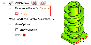
Based on the reference plane and the option selected in the More Conditions drop-down list, the sectioning plane will be defined.
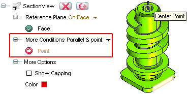
Once you have made the required selections the program generates the section view. You are also enabled to apply capping to the clipped area. You can control the visibility and color of the capping surface through the options under More Options.
 |
 |
| Section view |
Section view with the capping surface |
You can turn ON or OFF the Section View by selecting the  / options respectively from the context menu displayed by right-clicking in the Graphics area.
Note
After defining the Section Plane, when you start the command again, the options that you selected for Reference Plane and/or More Conditions are not remembered. However, the previously set Section Plane can be modified using the Depth handle. If you redefine the settings for Reference Plane and/or More Conditions, the Section Plane will reset. |
When you start the command, the AutoSnap functionality is temporarily disabled till the command is active. The program notifies you with the following warning message.
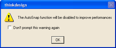
Disabling AutoSnap prevents unwanted snapping of the cursor while dragging the Depth handle to define the position of the sectioning plane, especially over large assemblies.

Enhancements in the Configuration Manager command
A new Reset command has been added to the existing list of the Configuration Manager commands. It enables you to restore the default configuration of the application, thereby losing all the changes that have been made to the current configuration. The default configuration is a snapshot of the application settings done after the installation at the first run time of the application.
It is important to note that the reset operation will have effect only when you restart the application. See the description of the command in the online help for further details.

The new Paste as Static command
This version introduces a new Edit Paste as Static command, which can also be started using keyboard shortcut — Ctrl+Alt+V. Using this command, it is possible to paste/import the stored object from the clipboard into the current or another document in a static way (which means without any history events).
The stored element is not removed from the clipboard when the Paste as Static command is used, so you can paste it more than once (in various positions and various documents), and remains in the clipboard until it is overwritten by another element.
The same functionality has also been made available in the Drag & Drop command. This can be achieved by holding down the Ctrl+Alt keys before releasing the mouse button to insert the object.

The smart selection commands simplify the selection of a set of entities that satisfy a given condition. The selections made by these commands are called semantic selection. In this version the following three new smart selection commands have been introduced:
This command is an enhancement of the previously available selection command. The new command enables you to select only a portion of the loop formed by a set of edges. It is available for the commands that accept the selection of curves inside solids.
The tangent chain command is started and used in a similar way as the command. To use this command you need to select only one edge. All edges forming a tangential chain with your selection are automatically selected.
The command assists you in selecting the faces in a group. It is available for the commands that require you to select faces.
See the online help for details and examples.

From this version onwards the Options tab of the Print Setup dialog box is called Print parameters. The Print parameters tab has also been restructured in order to increase its usability. The options in the tab are divided into two areas namely Print parameters and Exclude from printing, as shown in the image below:
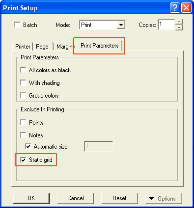
A new Static grid check box has been introduced in the Print parameters tab. Select the check box to prevent the printing of the static grid.

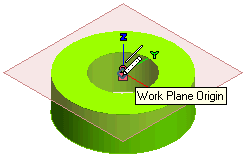
While working in the Model environment, it is now possible to snap to the origin of the Work Plane. This new snap functionality can be used for commands that accept point input. When you move the cursor over the Work Plane origin a snap marker appears along with the appropriate tool tip, as shown in the image below.

This version introduces new rendering functionalities. To log the information about the rendering parameters, the render data tree has been provided. Click here for details.

In previous version, the only possibility available to temporarily conceal the mini-dialog boxes which obstructed you from correctly evaluating the effect of the command preview or the geometry was the Hide Minidialogs command. From this version, it is also possible to drag and drop the mini-dialog boxes away from the geometry it is obstructing. To do so, click the left mouse button on the mini-dialog area, hold it down and drag the mini-dialog to a new position; release the mouse button when the position is reached. The result of this new feature is shown in the image below:

Please note that the mini-dialog will return to the default position if:
- You pan, rotate or zoom the model or drawing
- You change the view
- You edit the mini-dialog or drag its corresponding handle.

Enhancement in the Open File Command
Starting with this version, the Open in exclusive mode
check box has been introduced in the Options
dialog box of the
 command. This check box is available only while opening a Model (*.e3) or Drawing (*.e2) file. Also more importantly this check box is available only when Vault (an optional module of thinkteam) is not installed.
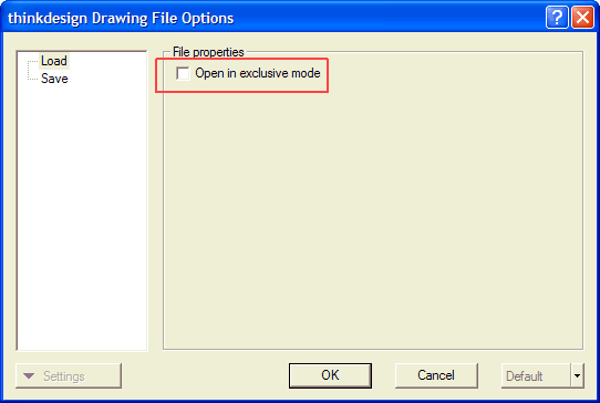
When the check box is selected, it locks the file. A locked file cannot be renamed or moved to a different location. The lock is released when the file is no longer used by the application.

Saving the display list with the Model (*.e3) file
The persistent display list is the visual display data that is associated with a Model (*.e3). To facilitate faster loading of the files, this version introduces the Save display data area in the Options dialog box of the  command.
Saving the display data affects the size of the saved file and the saving time. For this reason, this mode can be optionally disabled.
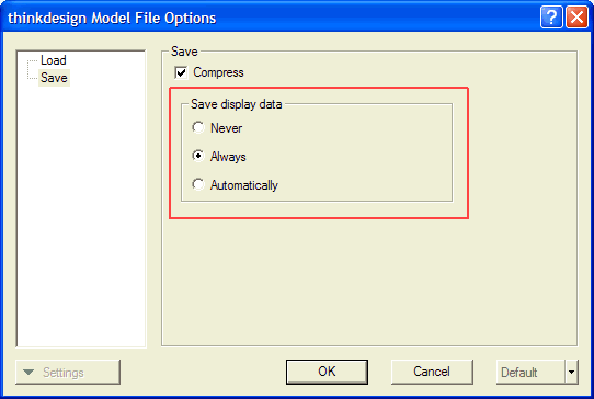
The Save display data area has the following new radio buttons:
- Never: a smaller file is generated as the display list will not be saved, but the file will take a longer time to load.
- Always: a larger file is generated as it contains the display list and it requires a longer time to save since the display list is always saved or updated, but the file is loaded faster.
- Automatically: lets the application decide when to save or update the display list, which is the optimal setup in terms of saving/loading time required.
Note:
These options are not available for Open in exclusive mode files. |
When the persistent display list is saved in Always or Automatically mode, the application checks for any odd tessellation parameters present in the model. You are warned while saving the model about the potentially wrong tessellation parameters in the Odd Display Parameters Report dialog box, as shown in the image below.
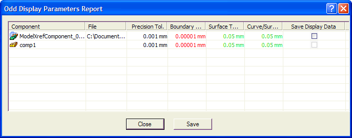
The dialog box displays different tolerance values of the model being saved. The values are displayed in different colors which indicating the following:
- Red - the tolerance value is odd (value may not be acceptable).
- Green - the tolerance value is not odd (acceptable).
Note:
The Save Display Data check box in the Odd Display Parameters Report dialog box is available only for X-Reference components and not for local components. |

New Model Quality command
The new Model Quality command (Tools Model Quality) enables you to check the quality of a model by searching for a number of issues that may be present in the model and that can be of topological nature, specific issues on curves, surfaces and points or also geometric problems.
After starting the command:
- Click Check Parameters in the selection list. The Check Parameters dialog box is displayed. This action is necessary only when you want to change the parameters and the warnings to be displayed.
- In the Select one or more items to check area, select the type of issues the command must detect by checking the corresponding box (Topological, On curves, On surfaces, Geometric). For example, if you check the Topological box, topological issues will be searched for; if you check the Geometric box too, also geometric issues will be searched for.
- Select the entities to be checked (Entities).
Right-click and select Continue to end selection. As soon as selection is completed, the Total Warnings item shows up in the selection list, indicating the total number of issues found in the selected entities, based on the types you have selected in the dialog box.
- In the Warning Category drop-down list, select the type of issues — among the ones that you have restricted the detection to in the above steps — to be displayed in the model.
| All Warnings |
To display all issues found, based on the detection choices you have done in the steps above. |
| Topological |
To display only topological issues. |
| On surfaces |
To display only issues related to surfaces. |
| On curves |
To display only issues related to curves. |
| On points |
To display only issues related to points. |
| Geometric |
To display only geometric issues. |
Once the category has been selected, you can also select a type.
- Click the
 button on top of the selection list.
An issue list will be displayed and you will be enabled to navigate forward and backward among the listed issues using the following arrows:
 |
Set next issue as the current one. |
 |
Set the last issue as the current one. |
 |
Set previous issue as the current one. |
 |
Set the first issue as the current one. |
- Under More Options the following options are available:
- Automatic Zoom
enables you to zoom on the zone of the model where the issues have been detected.
- When the box is checked, the zone of the model where the current issue has been detected is automatically zoomed so as to fit the current view.
- When the box is cleared, no zoom is performed.
- Set Target Position
enables you to move the target point to the center of the zone of the model where the current issue has been detected.
- When the box is checked, the target point is moved to the center of the zone of the model where the current issue has been detected.
- When the box is cleared, the target point is not moved.
Please note that whenever a file in a format other from the one of think3 is loaded, it is possible to choose whether to automatically run the Model Quality command on the geometry of the opened document.

The options available in the Parameter Area on starting the Rebuild Object command are now displayed in a separate dialog box.

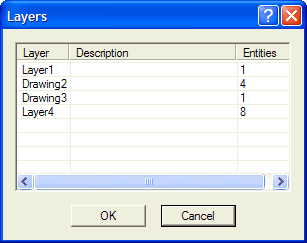
From this release onwards, the names of the layers are displayed in the Layers window for better usability. You can find the Layers window in the Page tab of the Print Setup and Print dialog box. The names of the layers displayed help you to select the required layer for printing.
You are also enabled to enter the names of the layers to be printed in the relevant edit box in the Print dialog box.
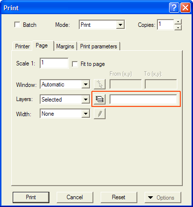
Enter the layer names separated by commas: name1, name2, name3.
You can also use wild characters such as name*, in this case the application prints all the layers matching the words preceded by the (*) symbol.
For example: when the word Draw* is entered in the edit box, then the application prints all the layers the name of which starts with the string Draw (Draw1, Draw2, Draw3 etc).


 World Axes command has been renamed as View
 Absolute Reference System (World) command.


 Mouse. In the Mouse Properties dialog box open the Pointer Options tab and see the options in the Motion area).


 button on top of the selection list.


