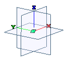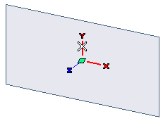
The 3 planes option under Planes area of the Reference Systems - Appearance category in System Options controls the display of the three planes. The XY-plane is the Work Plane.
Version 2008.1 introduces the following enhancements to the Work Plane editing and management.
From this version onwards it is possible to visualize all the three coordinate planes on the Graphics Area, as shown in the image below.

The 3 planes option under Planes area of the Reference Systems - Appearance category in System Options controls the display of the three planes. The XY-plane is the Work Plane.

The Work Plane editing methodology has been changed in this version. Previously the Edit Work Plane dialog box was used to define the various parameters for Work Plane positioning. Now this dialog box is no longer available. However, with the enhancements made in this version, new commands have been introduced and the functionality of many existing commands has been augmented to perform all kinds of Work Plane editing, that too in a more intuitive manner.
The following Work Plane editing commands present in previous versions of the think3 application will no longer be available henceforth.
Instead you can make use of the On Entity or the Select commands to get the required result.
Also note that the labels of the following Work Plane editing commands have been changed:
| Old name | New name |
| Set to World | On Absolute Reference System (World) |
| Set on View | On View |
| Set on Face | On Face or Datum Plane |
| Set on Profile | On Profile |
| Align to X | Align X-Axis |
| Align to Z | Align Z-Axis |
The display and appearance of the Work Plane are now controlled by the options of the System Options - Reference Systems and System Options - Reference Systems - Appearance categories. Previously they were controlled by the options in the Document Properties - Work Plane category, which has been removed henceforth.
| Note The Work Plane is now always visible during the redefinition of a "feature" that used a Work Plane element for its creation. (For example, the Work Plane axis could have been used to define the direction during a command's execution.) This way you can get the proper feedback (highlight) on the used Work Plane element. |

The On Entity command enables you to position the Work Plane over a selected entity. This command can be started in the following three ways:
 Work Plane
 On Entity
After starting the On Entity command you need to select an entity that can be profile, line, curve, surface, face or datum plane. Depending on the entity selected, additional options in the selection list will be displayed to define the origin and orientation of the Work Plane.

On selecting the Associative Mode check box, the Work Plane becomes associative with the entity that was selected to position it (only if the selected entities are associative). In such a situation, if the selected entity is transformed, the Work Plane also gets repositioned accordingly.
| Note You can select a curve inside a 2D profile to define the Work Plane only if the 2D Profiles check box is selected in the Inside area of the Customize AutoSnap dialog box. |

On starting the Move, the origin of the Work Plane gets selected. Now you just need to select another point to move the origin to it. You can also drag the origin to a new location. Note that while the origin of the Work Plane moves to the new point, the orientation of the Work Plane does not change. Once the Work Plane is moved, you exit the command automatically.
The Move command can also be accessed from the context menu displayed by right clicking on the Work Plane.

From this version the Align to X command is now termed as Align X-Axis. After starting the command you need to pick a direction to align the X-axis in the same direction. This can be done in two ways:
Note that while the X-axis of the Work Plane is realigned with the specified direction, the position of the Work Plane does not change.
The Align X-Axis command can also be accessed from the context menu displayed by right clicking on the Work Plane.
|

From this version the Align to Z command is now termed as Align Z-Axis. After starting the command you need to pick a direction to align the Z-axis in the same direction. This can be done by selecting a straight entity that can be either a line or an edge.
After the Z-axis has been aligned, you can optionally align also the X-axis by selecting a line or a point, as described in the previous topic. If you don't want to align the X-axis, press the ESC key to quit the command.
The Align Z-Axis command can also be accessed from the context menu displayed by right clicking on the Work Plane.

From this version the Set on Face command is now termed as On Face or Datum Plane. As the new name suggests, this command now allows you to not only set the Work Plane on a selected face but also on a Datum Plane.

A new Edit Work Plane
 Select command has been introduced in this version. This command enables you to quickly reorient and reposition the Work Plane. This command can also be started just by clicking on the Work Plane or by pressing Q on the keyboard.
On starting the Select command, translation  and rotation
  markers are displayed over each axis, and can be effectively used to transform the Work Plane.
The Select command is very versatile and offers you numerous methods to transform the Work Plane. Refer to the command description in the Online Documentation for details.

There are several methods to define a line, an axis or a direction, as stated in the "How to Define an Axis or a Line" document of the online help. Usually this is done by selecting a straight entity. At times, the program supports the selection of the coordinate axis as the straight entity. In previous versions, the coordinate axis selection in such situations was possible only by the explicit use of the X, Y, Z options from the direction/axis definition drop-down list.
With the enhancement made in this version it is now possible to select the axes of the Work Plane as the straight entity by directly clicking on them in the coordinate axes symbol displayed over the Work Plane (see the command Show Work Plane). To do so, choose the Line option (instead of X, Y, Z) from the drop-down list and then click on one of the axes, as displayed in the image below.

In this case, the direction is defined as the line parallel to the selected axis and passing through the origin of the coordinate system. However, you can change the origin by resetting the Origin selector and specifying another point the line must pass through, though retaining its direction.
Nevertheless, the method used in former versions is still available. A new Set direction/axes using X, Y, Z check box has been added to the Input category of the System Options so as to enable you to choose the method you feel more comfortable with.
(See also another example for the definition of a direction: "New Drafter command")

To execute some commands you need to define a plane. From this version onwards, apart from selecting a planar face or datum plane, it is possible to select one of the three coordinate planes for the Plane selector.
