 Curve Extend) enables you to modify the length of a selected curve by maintaining any of the following:
Version 2008.1 introduces the following enhancements to the Curve & Surface commands.
The new Extend Curve command (Modify Curve Extend) enables you to modify the length of a selected curve by maintaining any of the following:
| Minor UI changes in the Connect Curve command For the sake of homogeneity and to improve readability and user friendliness, some changes have been made in the user interface of the Connect Curve command. The former Continuity drop-down lists have been changed to Continuity By. The former Tangent option has been changed to Tangency. |

Significant enhancements have been made in the Offset Curve on Surface and Offset on Plane commands.
Starting from this version, when the Mode drop-down list of the Curve through Control Points is set to Edit control points and some control points have been selected, using some keys of the keyboard, you can directly move points along the direction of an axis. Proceed as follows:
| H | The horizontal direction of the screen (the cursor changes to following:  ). ). |
| V | The vertical direction of the screen (the cursor changes to following:  ). ). |
| D | The depth direction, that is the one perpendicular to the plane of the screen (the cursor changes to following:  ). ). |
| X | The X direction of the Work Plane (the cursor changes to following:  ). ). |
| Y | The Y direction of the Work Plane (the cursor changes to following:  ). ). |
| W | The Z direction of the Work Plane (the cursor changes to following:  ). ). |
Finally, note that starting from this version it is possible to increase the precision of the free-hand control point positioning mechanism as described in "Smooth point positioning using the mouse".
Significant enhancements have been made in the Rake Sweep command.
You have the possibility to select a set of surfaces to be used as the second drive only. The picture below shows the swept surface where the section remains tangent to the cylinder surface. The old Second Drive Curves selector has been replaced by the Second Drives drop-down list. See "Using the Rake Sweep Command along a Surface" in the online help for details.
You can select one side (or both) where the swept surface will be generated if the section is not located at an end point of the first drive. A specific handle is displayed in such cases:
For further details, see "Creating a Sweep Surface by Selecting the Side of the Motion" in the online help
The Associative Mode check box enables you to create those associative entities called Skins, that is open solids, which retain a link to the surfaces/curves they derive from (see "An Overview of Surfaces: Associative Surfaces (Skins)" in the online help for further details).
The command formerly known as Advanced Pipe has been renamed Pipe Surface, while the old Pipe Surface command has been removed.
In addition, self-intersections are now detected and pointed out through a specific warning message. In the following example the specified value of the radius is too big, thus causing the resulting surface to have a self-intersection. A specific message is then issued to warn you about this situation.
Please note that the same self-intersection detection mechanism is also enabled in the following commands:
Significant enhancements have been made in the Lofted Surface command.
It is now possible to manage also tangency and curvature continuity along the surface closures.
When the Close check box is selected, the Continuity mini-dialog box is displayed nearby. See "Managing Closed Curves with the Lofted Surface Command" in the online help for further details.
A new option is available under More Options. The Extend check box is displayed so as to allow the extension of the surface in the perpendicular direction to the boundary set. For further details see "Extending the Resulting Surface with the Lofted Surface Command" in the online documentation.
The following enhancements have been made in the Global Sweep command.
Associativity is now available also when the command is applied to a skin (Sweep drop-down list set to Surface). See the "Associativity" note in the command description of the online help for further details.
Specific warnings are displayed when self-intersections are detected. In the following example an ellipse has been swept along the drive curves and the resulting surface has a self-intersection which is automatically detected by the program.
When a Global Sweep is performed with several sections, starting from this version there are different ways to match their discontinuities (if any).
The new Section Matching node has been added under More Options. The Match Curve-to-Curve Sections option — already existing in former versions — has been moved here.
In the Matching type drop-down list, you can select the actual matching mode to be used by the application for the section mapping. See the command description in the online help for the available options and further details.
When the Motion Mode is set to Bi-driven, and when possible, the sections are scaled so as to keep in contact with the drives. Up to former versions, the scaling was isotropic. Starting from this version, a new Scaling drop-down list has been added to the selection list. See the details in the command description in the online help.
The new Rotational Sweep command is now available (Insert Surface Rotational Sweep). It enables you to create rotational sweep surfaces by revolving a set of sections
about an axis you can specify directly or let the program use a default one. Optionally, you can specify a set of drive curves which the rotational surface will have to follow. In addition, self-intersections are detected and pointed out through a specific warning message. See the complete command description in the online help and "Creating a Rotational Sweep Surface" for an example of usage.
The Curve Target Curvature command has been significantly improved. Target Curvature Curves with tangency discontinuity points can now be used: tangency discontinuity points will be taken into account in the computation to generate the plot.
In the following image the violet curve is the original curve, while the green ones are the curvature target curves.
And here is the result of the Curve Target Curvature in the new version.
Please note the differences in the curvature plots of the resulting curves between the former version and the current.
 |
 |
| Former | Current |
The "wave" effect obtained in previous version around tangency discontinuity points is no longer there so that the shape of the plot is much more compliant with that of the target curvature curves.
The new Full Round Fillet command (InsertSurfaceFilletFull Round) enables you to create a fillet tangent to three different surfaces.
See the online help for a complete command description.
| Removal of old Triple Fillet command The old Triple Fillet has been removed. The rare special cases handled by the old command can still be managed through the solid fillet commands, after converting the involved surfaces to solid entities. |
The new Cutting Line command (Insert Curve Cutting Line) enables you to perform the cutting step of the metal stamping process.
It computes the cutting line corresponding to the contour of the unbent wings along which the metal would be cut.
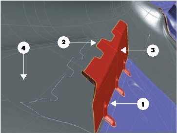 |
1 — Pivot curves 2 — Contour 3 — Base surfaces 4 — Target surfaces |
See the command description in the online help for further details on the command and "Creating a Cutting Line" for an example of how to use it.
Starting from this version, the Keep all arcs check box, available in the Intersect Curve, Project Curve, Section Curve and Light Contour Curve (Silhouette mode) commands, will show up only when necessary, that is only if small spans are actually detected in the resulting curves. The behavior of the check box remains the following.
The new Show Arc Joints check box has been added to the Convert Curve to NURBS and Convert Surface to NURBS commands. This option enables you to display a preview of the arc joints that you will obtain on the resulting NURBS entity. In case of surfaces, the option is active only after you have selected the Preview (  ) button.
A new option is now available in the Generic Shape drop-down list (enables you to select the best type of surface for your goals): Saddle curvature.
The surface you will obtain will be defined as a torus. You can define:
The Drafter command (Insert SurfaceDrafter) enables you to create surfaces along a drive contour and tangent to some other surfaces used as drives.
It can be used to add a draft angle to casting and forging parts.
See the online help for a complete description of the command and an example of use ("Creating Surfaces along a Drive Contour and Tangent to Some Surface Drives").
A significant enhancement has been made in the Surface through Control Points command. Starting from this version it is possible to increase the degree of the surface in both or just in one of the two parametric directions.
The Increase degree item has been added to the selection list.
When the editing mode (Mode) is set to Edit control points or to Add control points, clicking Increase degree causes the degree of the selected surface to be increased by one at each click in both directions, unless you have selected one "row" or one "column" of control points, in which case the increase will be applied only to the corresponding parametric direction (U or V respectively). The preview is immediately updated enabling you to interactively assess the possible result.
Starting from this version, it will be possible to select 3D profiles or curves inside 3D profiles within all the curve and surface creation/modification commands where it is possible to select a 2D profile or a curve inside a 2D profile respectively.