 Profile2D or 3D from the menu bar. Refer to the description of these commands in the Online Documentation to learn about other methods to start the profile environment and then returning back to the model environment.
This version introduces a new sketching functionality enabling the user to create 3D profiles. As a result the think3 application now supports both 2D and 3D profile environments.
| Note The "Profile environment" present in the previous versions of the think3 application is now termed as the "2D Profile environment". |
The 3D Profile environment enables you to create profiles in three-dimensions. Currently this functionality supports only straight line and point entities. 3D profiles can be very useful for creating the tubing path to be used by the Tubing functionality. Moreover, they can also be used for surface/curve creation and modification (if applicable).
You can start the required profile environment by selecting InsertProfile2D or 3D from the menu bar. Refer to the description of these commands in the Online Documentation to learn about other methods to start the profile environment and then returning back to the model environment.
You can control the display of the three tabs (Model, 2D Profile and 3D Profile) under the Graphics Area by making use of the Show tabs Model, 2D Profile and 3D Profile check box present under the Next model document area of the General - Advanced category in System Options. These tabs can be used to change the currently active environment.
The currently active profile environment is highlighted by the display of the corresponding icons (as shown below) on the top-right corner of the Graphics Area.


Those sketcher commands that produce or modify straight line entities can be used in the 3D Profile environment. Specific enhancements have been made in the Polyline command to ease the process of 3D entity creation. The Polyline selection list does not contain the Mode drop-down list when started in the 3D Profile environment as the creation of arcs is not supported here.
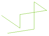
However, a new Work Plane on Last Point check box will be displayed. (This check box is displayed also when the Polyline command is started from the Model environment.) On selecting this check box, the Work Plane origin will be automatically moved to the last selected point to draw the polyline. Refer to the Creating a 3D Polyline document in the Online Documentation to learn more about the workflow of creating 3D profiles. An example of a 3D profile is shown in the image below.
| Note All the transformation commands can be used in the 3D Profile environment to move the entities. |
 |
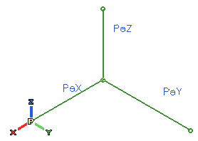
When you enter the 3D Profile environment, apart from the Work Plane and Absolute Reference (World) reference systems, you also have the Profile Reference System to which the 3D profile entities are referenced. It is represented by a P symbol at its origin. Refer to the Profile Reference System topic of the Reference Systems document in the Online Documentation for details. |
The line constraints applied to the 3D Profile entities is always in reference to the Profile Reference System. If the drawn line is parallel to any Profile Coordinate Axis, the parallel (Pa) constraint is automatically added with the letter corresponding to the axis suffixed to it, as shown in the image below.
The other constraints that can be applied to a 3D profile are:
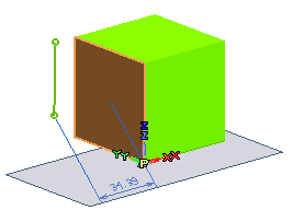
| Note The visualization of the geometric constraint symbols on the Graphics Area is always parallel to the current view, irrespective to the orientation of the profile (or the model). |
In the 3D Profile environment, it is possible to apply a dimensional constraint between a point and a plane. Starting the Smart Dimension command and selecting a plane and a point will apply the shortest distance dimension between the two entities. Also, all the other existing dimensional constraints apply the shortest distance between the two selected entities.
In the Model Structure, 3D profiles are represented using an Icon and labels that are different from the ones used for 2D profiles.
| Icon | Label |
| 2D Profile | |
| 3D Profile |
To edit a profile, you can right click on it in the Model Structure or Graphics Area and select Edit 2D Profile or Edit 3D Profile from the context menu. Double clicking on the entities in the Graphics Area will also activate the corresponding profile environment to facilitate their editing.
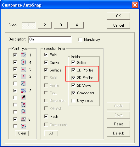
In the Customize AutoSnap dialog box, the new 2D Profiles and 3D Profiles check boxes have been added in the Inside area.

The following enhancement has been made in the 2D Profile environment.
This version introduces the new Offset constraint. This constraint can currently be applied only between lines and arcs. You can use the following two ways to apply the Offset constraint.
In the 2D Profile environment, if the Offset on Plane command is used with the Copies option selected, an offset constraint will be applied between the offset entities.
| Note In the previous versions, the Offset on Plane command was not enabled in the 2D Profile environment. However, from this version onwards it is enabled and you can use this command to apply Offset constraints between curves in the 2D Profile environment. Note that in the Transition drop-down list of the Offset on Plane selection list, only the None and Extend parameter options are present in the 2D Profile environment. |
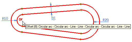
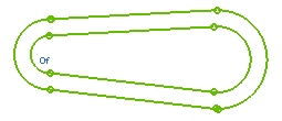
On the profile, the Offset constraint is represented by the 'Of' symbol. Moving the mouse over this constraint will display:
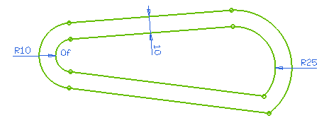
If the orientation of any of the curves involved in an offset constraint is modified, the remaining curves are realigned to maintain the offset distance, as shown in the image below.
The new Offset constraint can also be applied directly by using the InsertProfileOffset command. On invoking this command the Offset Constraint selection list is displayed.
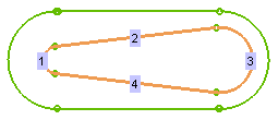
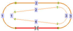
You need to select two groups of entities (for the First Group and Second Group selectors respectively) between which the Offset constraint is to be applied. The entities selected in the first group and the corresponding selection in the second group should be of the same type, as shown in the images below.
 |
 |
| First Group | Second Group |
 |
|
| Result | |
| Note On selecting the Add Dimension check box, the offset dimension can be applied between the entities that can be later modified to redefine the offset distance. |