Drafting and Dimension Enhancements
Version 2008.1 introduces the following enhancements to the user interface and functionalities of the drafting commands.
New user interface of the Text command
A new user interface with a selection list replaces the old Parameter Area of the Text command that now features the following new options:
| Origin/ 2 Points |
Enables you to select one or more positioning points and to specify the type of justification both for single and multiline texts.
The selector will change to 2 Points when justifications requiring two points are selected in the drop-down list: Fit & stretch, Align & scale. All the other justification types will cause the selector to show Origin and require just one input point. Refer to "Align" in the online documentation for further details on the list of available justification types. |
| Text from Dictionary |
Offers a set of predefined texts organized for two different contexts:
- Document properties
- Component properties
When you expand the node, a dialog box shows up, displaying of all the available predefined text for the selected context. You can double-click any of the list items to make it the current text content. |

New user interface of the Move and Modify commands
The old Move/Modify dimension command has been split into two separate commands — Move and Modify.
In addition to being more consistent with the application standards, the two new commands enable you to perform modifications much more easily and quickly. Finally, the navigation from the Move command to the Modify command has been made much easier.
As a result, the old Parameter Area of these commands has been removed.
New functionalities
- From this version, double clicking on a dimension will start only the Move command. This will facilitate the movement of the measure line or text and the change in length for the witness line.
The command can be started both from context menu of a preselected dimension and from the menu bar (Modify Dimension
 Move).
- The new Modify Dimension command will display a selection list which depends upon the type of entity selected:
The command can also be started by preselecting a dimension entity and selecting any of the following:
- Modify Dimension (
 ) toolbar button
- Modify
 Dimension
 Modify command
- Modify Dimension command from the context menu
- It is also possible to perform the Modify Dimension command functionalities when the Move command is active. To do so:
- Start the Move command.
- Select a dimension text or a witness line.
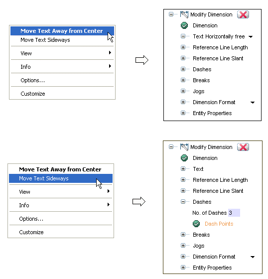
- Then, right-click on the Graphics Area. A context menu will be displayed showing the relevant options belonging to the part of the dimension selected.
The context menu commands change depending on the following type of selections:
Dimension text
When you double-click a dimension text, depending on the option you select in the context menu, the Modify Dimension command displays the selection list that follows:
Dimension witness line:
When you double-click a dimension witness line, depending on the option you select in the context menu, the Modify Dimension command displays the selection list that follows:

New user interface
The Modify Dimension command has been provided with a new selection list that contains different options for which the handles will appear conditionally depending on the node selection. The selection list is shown in the image below:
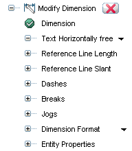
The functionalities of the options available in the image shown above are:
| Dimension |
Enables you to select the dimension to be modified. |
| Text |
Enables you to choose the options controlling the movements of a dimension text.
| Horizontally free |
The text will move along the measure line freely. |
| Horizontally constrained |
The text will move along the measure line only at the four restricted points as shown in the image below:

` |
| Away free |
The text will move away from the measure line freely. |
| Away perpendicular |
The text will move away from the measure line with perpendicular leader. |
|
| Reference Line Length |
Enables you to modify the reference line length freely.
- When the node is expanded, a handle associated with the Gap mini-dialog box will be shown at the start of the reference line. Using either mini-dialog or handle, it is possible to change the length of the reference line freely.
|
| Reference Line Slant |
Enables you to rotate the dimension line and text freely.
- When the node is expanded, a handle associated with the Slant mini-dialog box will be shown at the start of the reference line. Using either mini-dialog or handle, it is possible to change the angle of the reference line freely. The maximum permissible angle is 45 degrees.
|
| Dashes |
When selected, expands to show the following options:
- No. of Dashes Enables you to enter the number of leader line segments.
- Dash Points Enables you to specify the positioning points for the leader line.
|
| Breaks |
When selected, expands to display the following options:
- 1st break When selected, expands to show the following options:
- Two Points Enables you to select two points to insert the first break.
Similarly, it is possible to insert up to four breaks using the respective options in the list.
|
| Jogs |
When selected, expands to show the following option:
- Two Points Enables you to choose two points for the jog insertion.
|
| Dimension Format |
Enables you to choose a dimension format to be applied from the drop-down list. When selected, the node expands to show the options to make customization. For details on the options, refer to the online documentation. |
| Entity Properties |
Displays the Entity Properties dialog box that enables you to edit the dimension properties. |
The program displays the Modify Dimension selection lists shown below depending upon the type of selection made:
- Entity with leader line
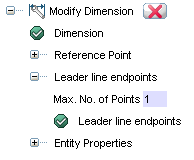
- Entity without leader line

The functionalities of the options available in the images shown above are:
| Dimension |
Enables you to select the dimension to be modified. |
| Reference Point |
Enables you to select the reference point that identifies the component that is referenced by the dimension. |
| Leader line endpoints |
Enables you to redefine the position of the leader line point on the drawing area.
- No. of Dashes Enables you to specify the number of leader line segments.
- Dash Points Enables you to specify the positioning points for the leader line.
|
| Text |
Enables you to edit the label (one without leader line points). |
| Entity Properties |
|

New user interface of the Label command
The Label command is now displayed in the application Graphics Area. This command has been removed from the old Parameter Area, thereby providing maximum workspace.
Due to this version enhancements of the Balloon commands, moreover, the Balloon button that appeared in the Parameter Area has not been inserted in the selection list.

New user interface of the Surface Textures command
The Surface Textures command is now displayed in the application's Graphic Area. In previous versions, the command was displayed in the Parameter Area, which is now removed to provide maximum workspace.
The following new options are available under More Options.
| Text only |
Enables you to insert the surface texture symbol without selecting a reference entity to attach it to. |
| Plane |
Enables you to choose the plane onto which you want the surface texture to be inserted (Work Plane, View, World). This option is available only in the 3D environment. |

New user interface for the Feature Control Frame, Datum Reference and Datum Target commands
The Feature Control Frame, Datum Reference and Datum Target commands have undergone significant improvements.
- They have been introduced as individual commands from the menu bar (Insert
 Dimension).
- They are also available from the Commands - Dimension category of the Customize dialog box (Tools
 Customize).
- Their interface has been renewed to make them consistent with the application standard. A new selection list has been developed in the Graphics Area for each command.
- To provide maximum work area and maintain consistent usability, the old Parameter Area has been removed.
- In previous versions, though it was possible to insert a feature control frame or datum reference without any reference to an entity, there was no option visible to notify the user about its availability. Now, a new Text only option has been added to the selection list as a part of feature refinement.

New user interface of the Quick Move/Copy Entities command
From this version, on starting the Quick Move/Copy Entities command opens a new dialog box. All the command options in the old Parameter Area are now moved to the new dialog box. As a result the old Parameter Area is removed, thereby providing a larger working area.

Improvements in the Hole Table command
In this version, the management of the Hole Tables has been completely renewed.
- The Hole Table command selection list has been completely revised. This improved user interface is extremely friendly and easy-to-use.
- The customization interventions such as parameter settings, format choice and so on have also been extremely simplified. They are now very easily and interactively performable through a dedicated interface that is reachable in both of the following ways:
The Organize Hole Table – Options dialog box enables you to customize all the settings involved in the Hole Tables rather than accessing and editing external files as you had to do in former versions.
- Now, it is possible to quickly edit or redefine a Hole Table without removing and recreating it again as it used to be in former versions. To facilitate this operation, a specific command can be started in one of the following ways:
- Modify
 Dimension
 Hole Table
- Modify Hole Table (
 ) toolbar button.
- Right-click on the Origin Symbol or Hole Table and select Modify (
 ) command from the context menu.
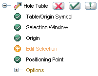
When the command starts, you are prompted to select the entity (either the Origin Symbol or the Hole Table). On selecting the required entity, the current selection list will be updated as shown in the image below:
- In order to customize the current configuration settings of the Hole Table, a new Organize Hole Table – Options dialog box has been developed, as shown in the image below:
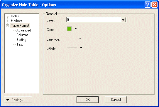
For more information on the options in the Organize Hole Table – Options dialog box, click here.
This dialog box can be activated in two different ways, as listed below:
- From the command selection list itself by expanding the Options node
- Format

 Hole Table
As a result of this improvement, the old procedure of editing the HTable.ini file in the files/drawing subfolder of your installation folder has been eliminated.
- From this version the Hole Table selection list has been enhanced as shown in the following image:
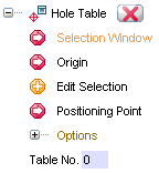
| Selection Window |
Enables you to use a window selection for multiple hole selection. |
| Origin |
Enables you to determine the point with respect to which the (X,Y) co-ordinates of the Hole Origin will be calculated. |
| Edit Selection |
Enables you to edit the selection. You can deselect any number of holes from the selection window. |
| Positioning Point |
Enables you to specify a point where to position the customized Hole Table at. |
| Options |
Displays the Organize Hole Table – Options dialog box for customizing the current configuration settings. |
| Table No. |
Enables to enter the Hole Table number. Helpful to discriminate a table among multiple tables. |
- A new Hole Table command (Format
 ) has been added. When started, the command displays the Organize Hole Table – Options dialog box. This dialog box provides all the options and commands necessary to create new settings and also organize the existing ones. On opening the dialog box for the very first time, it opens with the default setting; all subsequent times, it opens with the last saved configuration for the current drawing file. It is also possible to redefine the current setting configuration and save it to the library with a new name. To do so, follow the steps stated below:
- Make the necessary changes to the Hole Table parameters and select the Settings button on the bottom left corner of the dialog box.
- Select the Save New Settings to Library option.
- Now specify a name for the new settings file in the corresponding dialog box and click OK.
- To manage the existing settings, click the Organize Settings option from the Settings button. A Organize Settings dialog box will be displayed.
Here, you can create new setting files (using the New button), rename the existing setting files (using the Rename button), load another configuration file to initialize all the fields with the current setting data (using the Load button) and delete the selected setting file (using the Delete button).
-
Note
Should any of the old customers want to use the old command for any reason of their own, it will be enough to type the following string in the I/O window (and press ENTER) to start:
User::tdHoleTable |
Organize Hole Table – Options Dialog Box
The following are the categories in the dialog box:
Holes:
The Holes category enables you to customize the hole types.
| Type |
Enables you to choose a hole type. The list items are available based on the configuration file. |
| Description |
Enables you to specify a text description to be displayed in the Description column. You can also use this field to display the primary and secondary diameter information of the corresponding Hole by using the two customized symbolic texts <D1> and <D2>. |
| Marker label |
A specific text input to be used along with the Marker for the Hole type. This text will be concatenated to the original Marker to distinguish the Hole Type. |
Markers:
This category enables you to define the hole markers.
| Display format |
This area enables you to select one of the three display formats, which will get appended to any specific marker value provided in the respective Hole Definition file.
| A B C D |
When selected, displays only letters in a sequential order (A-Z; AA, AB-AZ; BA, BB-BZ etc). |
| 1 2 3 4 |
When selected, displays only number values in an incremental order. |
| A1 B1 C1 D1 |
When selected, displays the letters along with the Hole Table number in an incremental order of the alphabets. |
|
| Position |
Enables you to choose the option (Top left, Top right, Bottom left, Bottom right) to position the marker with respect to circle center. The marker will be placed outside/inside depending on the bounding box size of the Marker text. The marker positions are shown in the illustration below:
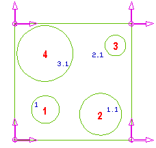 |
| 1 |
Top left |
| 2 |
Top right |
| 3 |
Bottom left |
| 4 |
Bottom right |
|
|
| Offset |
Enables you to specify the value (greater than zero) to be used for the placement of the Marker label with respect to the default position; applied only when the marker is outside the circle. |
Table Format:
The controls in the General area enable you to define the following parameters used by the application for creating a Hole Table:
| Layer |
Enables you to specify the layer in which all the entities related to Hole Table will be placed. |
| Color |
Enables you to determine the color to be used for creating the Hole Table related entities, like the Table Line, Marker Label etc. |
| Line type |
Enables you to determine the line type to be used for drawing the Hole Table. |
| Width |
Enables you to determine the line width to be used for drawing the Hole Table. |
Advanced:
This category enables you to control the visualization of the Hole Table.
| Header/footer |
This area controls to customize the Header and Footer section of the Hole Table.
| Header |
Enables you to specify simple or formatted text (TML) to be used as the table header. |
| Footer |
Enables you to simple or formatted text (TML) to be used as the table footer. |
|
Save to CSV file
The area enables you to save the Hole Table data in a .CSV file format under the user directory.
| File name |
When the check box is selected, the application automatically creates a .CSV file for every Hole Table creation thereby overwriting the existing file without any prior warning.
Enables you to specify the file name in the adjacent text box. If not specified, the name will be automatically taken by concatenating the table number to the drawing file name with underscore as separator (for example: HT_0.CSV, HT_1.CSV). |
Columns:
This category enables you to customize and format the table columns to be viewed on the Hole Table.
| Available |
Displays the available list of columns. Using the arrow buttons, you can move them to the Used list. |
| Used |
Displays the currently used list of columns. Using the arrow buttons, you can remove them from the Used list. Using the up/down buttons, you can arrange the columns in the required order. |
| Title |
Enables you to specify the text to be shown in the Title section of the respective column. You can insert TML syntax to represent a symbol along with the title description. |
| Align title |
Enables you to assign the alignment (Left, Center, Right) to the title text. |
| Width |
Enables you to specify the maximum field width for the column. The column width entered by the user will be considered only when the value is greater then the minimum width required for inserting complete data without any data loss. |
| Align data |
Enables you to assign the alignment (Left, Center, Right) to the column data. |
| Decimal digits |
Enables you to choose how many decimal digits to display. |
| Property |
Enables to insert a property class (UDC-User Defined Class) name to assign the property value in the respective column. |
Sorting:
This category enables you to manage sorting criteria for the Hole Table command.
Note
For individual Hole Type, the user option for sorting order will be applied; that is, first the table data will be sorted with respect to the Hole Type, and then each Hole Type entry will be sorted with respect to the sorting criteria set by the user.
|
| Type |
Enables you to choose an ordering option for the sorting criteria. |
| Diameter, X, Y |
When selected, a specific column will be numbered in the order of selection, say 1, 2, 3.
When not selected, it takes the Diameter, X, and Y as the default sorting criteria. |
Text:
This category enables you to control the Text style to be used and some inputs related to formatting.
| Name |
Enables you to determine the Text style to be used for the current Hole Table configuration. |
| Measurement unit |
Enables you to determine the unit of measure for the current Hole Table configuration.
When None is selected, the measurement units being set for the current document will be applied.
|
| Zero display |
The options in this area enable you to determine the visibility of the Leading and Trailing zeroes.
| Leading |
When selected, the Leading zeroes are visible. |
| Trailing |
When selected, the Trailing zeroes are visible. |
|

New Dimension Properties toolbar
The new Dimension Properties toolbar enables you to quickly edit or define a limited set of properties of dimensions and texts. The tools are designed to offer you a quick access to the most used dimension and text properties.
Use the Toolbars tab of the Customize dialog box to display the default Dimension Properties toolbar.
Note that the program remembers the status of the toolbar:
- If you close it, you will have to open it manually when you need it.
- If you open it, the program displays it at all times.
- If you select one or more dimensions, then open the Dimension Properties toolbar, the program closes it when you deselect the dimensions. It will open it again automatically when you again select a dimension.
In the default configuration, the toolbar provides you with the tools to control properties such as:
- The Linear Dimensions Arrow type and the visibility of witness lines
- The Dimension Text size
- Text effects such as underlining, parentheses and orientation
- The presence of the Radius symbol in radius dimensions, of the Diameter symbol in linear dimensions, and of the Symmetry symbol in linear and diameter dimensions
- The Measure prefix and suffix
- The Tolerance format and content
When you rest the cursor on the toolbar commands, the program displays a tooltip with a short description of the command.
At the bottom of customizable drop-down lists you find the Edit command that enables you to edit the list of values available. The program makes the changes immediately available to you and stores them permanently.
The toolbar commands act differently whether there are preselected entities or not:
With preselection
When you preselect a dimension or text, the toolbar reflects the properties of the entity; when you select multiple entities, only common values are displayed, while the others are blanked. Non applicable properties are disabled.
When you change a property, all preselected entities are assigned the value you have specified.
Without preselection or while inserting entities
When no entity is selected, if you use one of the commands in the Dimension Properties toolbar to set a property to a certain value, the entities you then insert acquire the value you have specified until you reset it.
The properties you set with the Dimension Properties toolbar commands override the current style property values for the entities involved. The overridden properties are displayed in bold in the entity properties dialog box.
Use the Reset to Style command to restore the entity style if you need to. |
Dimension Properties toolbar customization
The Dimension Properties toolbar is fully customizable. You are also enabled to create new ones. Use the Customize command to add and remove buttons to the existing Dimension Properties toolbars. Note that although you are enabled to add any command to a Dimension Properties toolbar, only dimension or text properties will operate as described above.
A powerful new command has been introduced in order to enable you to have full control of the customization of existing Dimension Properties toolbars and to enable you to create new ones. You can find the New Toolbar Object command in the context menu of the properties of the Dimension and Text categories of the Entity Properties. Refer to the online documentation for a detailed description of the New Toolbar Object command.
When you execute the Customize command and you right-click on the toolbar background, the new Use Block to Align command is displayed in the context menu. This command enables you insert non-functional blocks of various sizes that are designed to serve as place holders or separators for the alignment of the objects in the toolbar.

New user interface of the Automatic Balloons command
A new selection list has been introduced for the Automatic Balloons command.
The new Balloon Format option enables you to select one of the available balloon formats that you can manage with the relevant category of the Formats command.
By expanding the branch, you are enabled to customize the text, frame and arrow type of the selected format. This setting does not survive the command completion.

New user interface of the Manual Balloons command
A new selection list has been introduced for the Manual Balloons command that replaces the former toolbar that contained the format selection.
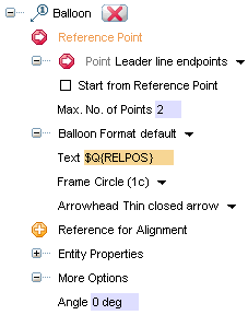
The command selection list contains the following options:
| Reference Point |
Enables you to select the reference point that identifies the component that is referenced by the balloon. |
| Point |
Select from the drop-down list where the balloon insertion point should be referenced:
- Leader line endpoints
- Text origin
|
| Start from Reference Point |
Available when Point is set to Leader line endpoints, enables you to select the referenced part and the balloon starting point in one click. |
| Max. No. of Points |
Enables you to define the maximum number of points (and, therefore, segments) that make up the reference line. Although you are always enabled to right-click and insert the balloon with fewer points, when you have entered the required number of points the program inserts the balloon. |
| Balloon Format |
Select from the drop-down list the format among those you have defined using the Formats command that now features a balloon section.
After selecting the balloon format, you are enabled to customize it for the current command session with the Text, Frame and Arrowhead. |
| Reference for Alignment |
Enables you to select an existing balloon to be used as alignment reference. While inserting a series of balloons, click Reference for Alignment and select an existing balloon. The balloons you next insert are aligned vertically or horizontally depending on their relative position. |
| Entity Properties |
Displays the Entity Properties dialog box that enables you to edit the balloon properties. |
| Angle |
Enables you to specify the balloon text angle with respect to the X-axis. This option is visible when the More Options branch is expanded. |

Keyboard shortcut key to block mini-dialog values
This version introduces a new keyboard shortcut key — B — to block the value displayed in a mini-dialog box of any drafting command. Refer to Blocking mini-dialog values through the keyboard for more details.

Enhancements in the Formats command
The Formats command dialog box includes a number of enhancements due to this version new features.
In the General category, the Layer text box has been replaced with an editable drop-down list in which you can choose an existing layer.
The new Balloon category features the General category that contains the following properties for the active Balloon format:
| Text |
Check the check box to enable the field in which you can type the Balloon label for the current format. See the online documentation on details on how to customize the Balloon label. |
| Frame |
Check the check box to enable the control and select from the drop-down list the frame style to be used in the current format. |
| Arrowhead |
Check the check box to enable the control and select from the drop-down list the arrow style to be used in the current format for the Balloon reference line. |

 Dimension
 Move).
 ) toolbar button
 Dimension
 Modify command


 ) toolbar button.


