New Layout Functionalities and Improvements
Version 2008.1 introduces the following enhancements to the Layout commands.
User interface improvements in Layout commands
The user interface of the Layout commands below listed has been significantly improved, while the command functionality has been kept unchanged. They have been made homogeneous and consistent, thus increasing readability and accessibility. As a consequence, a new selection list has been introduced and the old Parameter Area has been removed to provide a larger working area.
Detail View:
The user interface has been completely renewed for this command. A selection list is now available.
- The bound of the detailed view can be chosen using the Boundary drop-down list.
- The bound types are Rectangle,
Circle and
Spline.
- The Place View option has been added to position the final view in the Graphics Area.
Draw as Group:
Most of the old Parameter Area items are now available in the new user interface — Draw Section as Group selection list — of this command.
- The selection list will resemble the Define on Drawing command. The only difference is it will create a different group with the name given by the user.
- The old HV option has been renamed as
Horizontal vertical in the
Orientation drop-down list.
- Now, it is possible to reverse the direction of the cutting plane arrows in two ways:
- double clicking on the marker (red arrow) available on the very first point selected
- selecting the Invert check box, available in the selection list
Half Break on View/Section:
From this version, the old commands Half Break on View and
Half Break on Section have been unified to
Half Break on View/Section. A selection list is now available.
- The drop-down list Reference Point On enables you to choose a point on a View or Section for which the break should be applied.
- The four different types of bound types are listed in the Region drop-down list.
- Once you have chosen the bound types, a handle/mini-dialog box pops up to enable you to define the geometric parameter either by dragging the handle or by entering the measure value.
Partial Break on View/Section:
From this version, the old commands Partial Break on View and
Partial Break on Section have been unified to
Partial Break on View/Section in the following cases:
- Insert
 Break Lines
 Partial Break on View/Section
- Modify
 Drawing View
 Partial Break on View/Section
A selection list is now available for both the insertion and edit mode.
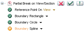
- The drop-down list Reference Point On enables you to choose a point on a View or Section for which the break should be applied.
- The three different types of bound types are listed in the Boundary drop-down list.
- Once you have chosen the bound types, a handle pair pops up to enable you to define the geometric parameter by dragging the handle.
- Just like in the old commands, it is possible to define multiple partial breaks in a current view/section. To facilitate this, a new Boundary node will be generated automatically on completion of every bound selection as shown in the image below:

Edge Visibility:
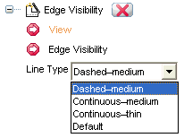
The user interface of this command has been renewed as shown in the image below:

- From this version, you need not end the command to apply it to another view. To facilitate this, the View selector has been made available in the new selection list.
- Now this command will allow multi-edge selection at a time using any of the selection commands: ,
,
,
.
Hide Dimensions Axes Edges:
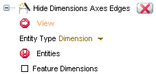
The renewed interface of this command is shown in the image below:

- From now onwards, the number of hidden entities will be shown as a part of description in the status bar.
- The check box For selected feature has been renamed as
Feature Dimensions. Select All has been removed since all the selection modes like ,
,
,
are allowed.
- The concept of Layer has been removed as it can be used simultaneously with any other command.
Unhide Dimensions Axes Edges:
- This command will have the same selection list as the Hide Dimensions Axes Edges command, which enables the user to unhide hidden entities.

Improvements in the Multibreaks on View command
The command formerly known as Multi-Broken View command has been renamed to Multibreaks on View in the following cases:
- Insert
 Break Lines
 Multibreaks on View
- Modify
 Drawing View
 Multibreaks on View

New visualization in the Custom View Definition dialog box
On opening a file containing Sheet Metal Wizard components in the Custom View Definition dialog box, the parent solid remains hidden in it. Please view the New Sheet Metal functionalities and improvements document for details.

Drawing views for the Tubing parts
The components generated by the Tubing functionality are supported in the Drawing environment and hence, their drawing views can be generated (as for any other model).

 Break Lines
 Partial Break on View/Section
 Drawing View
 Partial Break on View/Section
 Break Lines
 Partial Break on View/Section
 Drawing View
 Partial Break on View/Section


 Break Lines
 Multibreaks on View
 Drawing View
 Multibreaks on View

