Version 2008.1 introduces the following enhancements and improvements to the Sheet Metal functionalities.
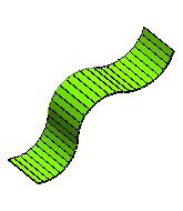
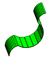
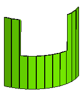
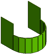
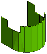
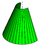
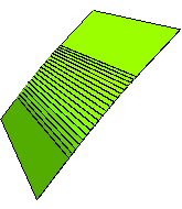
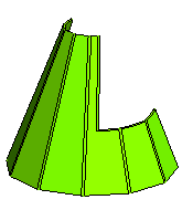
The improvements made to the Step Bend command now enables it to support the following situations encountered (that were not previously supported) while creating step bends on cylindrical and conical faces.
 |
 |
 |
| Cylindrical face tangent to other cylindrical faces | Cylindrical face not tangent to other cylindrical faces | Cylindrical face having a slot |
 |
 |
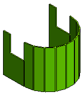 |
| Cylindrical face tangent to flat faces with a slot on the cylindrical face exactly at the tangent edge | Cylindrical face tangent to flat faces having a slot across the tangent edge | Cylindrical face tangent to flat faces with a slot on the flat faces exactly at the tangent edge |
 |
 |
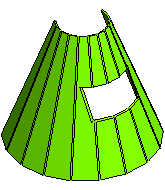 |
| Normal conical face with constant angle | Conical face tangential to flat faces | Conical face having a fully enclosed slot |
 |
 |
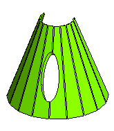 |
| Conical face having a slot across an edge | Conical face having a slot across two edges | Conical face having an elliptical slot |

Handling of rips by the Sheet Metal Wizard has been made stabler. As a result, the following situations are now successfully managed:
It is now possible to specify the Type of rip that is created by the Sheet Metal Wizard (as it happens in the Edge Rip command). The Type mini-dialog box is displayed on opening the Local Properties node of the Rip Group in the Sheet Metal Wizard selection list.
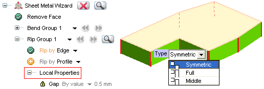
Using the Type drop-down list you can specify whether to create a  Symmetric,
  Full or
  Middle rip. In case of Full/Middle rip, red arrows will be displayed on the rip edges to specify the direction of material removal.
The situation where the rip is to be created at the vertex of two tangent edges is now successfully managed by the Sheet Metal Wizard.
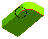 |
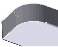 |
| Situation | Result |
The situation where the rip is to be created at the vertex of a linear and a non-linear edge is now successfully managed by the Sheet Metal Wizard.
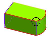 |
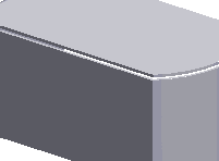 |
| Situation | Result |
The situation where the rip is to be created at the vertex of two or more linear edges is now successfully managed by the Sheet Metal Wizard.
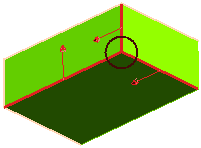 |
 |
| Situation | Result |
The situation where a sketch rip is to be created at a vertex is now successfully managed by the Sheet Metal Wizard.
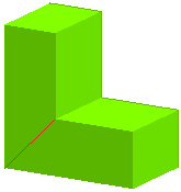 |
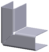 |
| Situation | Result |

In this release there have been improvements in the way the think3 application manages Sheet Metal Wizard components.
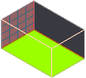
During the process of applying the command, the preview of the current component is now highlighted by a grid over it. This makes it easy to notice the current component in the graphics area.
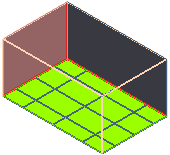 |
 |
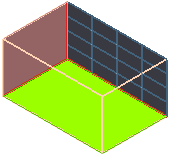 |
| Resulting component 1 | Resulting component 2 | Resulting component 3 |
Using the navigation buttons  of the Resulting Components option in the Sheet Metal Wizard selection list, the highlighting of the current component will cycle.
On applying the Sheet Metal Wizard command, the parent solid is automatically hidden and only the resulting sheet metal components are visible.
| Note The think3 application treats the Sheet Metal Wizard components differently as compared to the assembly components and hence, some assembly command functionalities cannot be applied on them. As a result, the following warning is displayed for commands like Replace Component, Break Component, Unload Component etc, when applied to the Sheet Metal Wizard components. 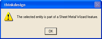 |

With the enhancement in the Solid Flange command, the thickness dimension will be visible on the created flange. This is a driving dimension and hence can be modified to change the flange thickness parametrically.
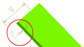
| Note In case the thickness dimension is not visible make use of the Show Driving Dimensions command. |

This version onwards, on opening a file containing Sheet Metal Wizard components in the Custom View Definition dialog box, the parent solid remains hidden in it.
