Overview on Mold Base
The Mold Base commands enables you to create the mold base for the creation of core and cavity. The mold base is an assembly of plates and is created completely by an automated process to facilitate mold designing.
There are five commands which represent the different Mold Base supplier. After creating the core and cavity (along with the inserts if required), you can build the mold base assembly using the various available catalogs. The catalogs are provided by the mold base suppliers (vendors) are represented by five new commands DME, HASCO, Meusburger, Pedrotti, and Futaba.
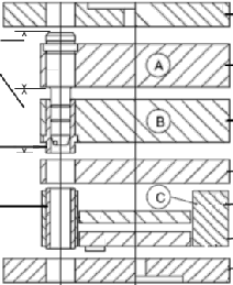
The mold base assembly mainly consists of the Top Plate, Cavity Plate, Core Plate, Core Back Plate, Spacers and Bottom Plate as shown in the image below.

The following is a brief description of the functionality of different plates.
| Top Plate |
This plate is attached to the fixed part of the molding machine and supports the Cavity Plate. |
| Cavity Plate |
This plate has the cavity form and slide cores of the mold. Also called as A plate and is aligned to the core plate. |
| Core Plate |
This plate is attached to the movable part of the molding machine which has the core form of the mold and is also called as B plate. |
| Core Back Plate |
It supports the core and cavity plates and acts as a back up plate. |
| Spacers |
This plate is placed between the movable Bottom Plate and the Core Plate. This plate provides space and allows the plate to move while ejecting the mold part. |
| Bottom Plate |
This plate acts as a base plate and is attached to the movable part of the molding machine. It supports the Core Plates, Spacers and Core Back Plates. |
Additional plates like floating plate or stripper can also be inserted in the Mold base assembly.
Note
- The catalogs have to be installed to create the mold base.
- The origin of the Work Plane is taken as reference for creating the mold base. The origin is positioned exactly at the middle of the core and cavity.
|
In some case it is useful to have three guide pillar with the same diameter and the 4th with another diameter. In order to allow this choice the 3 + 1 option for Leader Pin Top Shank and Leader pin busings is available in the Guide Elements tab of the DME and MEUSBURGER catalogs.
If the 3+1 option is No, all the four leader pins have same diameter. If it is Yes, three leader pins have same diameter and the 4th has a lesser diameter. The 4th leader pin will be placed at lower right of top view.
In order to access the said features in the DME, HASCO and MEUSBURGER catalogs you have to import the ones available starting from version 2014.1.
Try to ...
