Sometimes the "casual" use of the program can generate 3D models that have unexpected behaviors if dimensions are changed or profiles are edited. Sometimes it can even generate unexpected shapes when inserted into assemblies.
The following example shows a mechanical object, which, after simply dragging the profile that drives the initial base solid, is completely distorted.
|
|
This can be due to an incorrect use of the Work Plane, such as, moving it on a face and then unlinking it from that position before sketching the following profile.
See Tips on how to get the most from your Work Plane's history.
Before beginning, unhide all the profiles. You know that every profile has its own Work Plane (see Managing Links between the Work Plane and a Profile).
The best way to fix the Work Plane history is the following:
Then, the idea is to reassign a Work Plane to the profile. A typical mistake is to assign a Work Plane that "was born" after the profile by using the Move/Copy to Current Work Plane command. Doing so, you'll get the warning Loop detected which means that the Work Plane you are trying to assign is dependent on something that was "born" after the profile itself.
The best way to avoid the warning is to rollback one more step, until the Profile disappears, and then place the Work Plane on that face.
Notice that the history of the model is still "alive", though "suspended":
At this point, you have to Roll Forward all the history. At the end you will have to reassign the current Work Plane (the one just placed) to the Profile to be fixed. Using this technique, profile by profile, (if needed), you can rebuild the hidden history of the Work Planes.
Next step is to check if the profiles are correctly constrained to the solid itself.
Then everything will be fixed.
Reassuming:
 Work Plane
On Absolute Reference System (World)
Work Plane
On Absolute Reference System (World)On the other hand, sometimes a model is too complicated to try to fix it with the above method. This can happen especially when editing a model that has been created by someone else. In this case, a quicker solution is the following.
Suppose that, after editing the first solid, we got unexpected modifications of the slots. See the highlighted faces on the right side. They are no longer parallel or perpendicular to the bottom face of the solid.
 |
 |
Since the blind slot appears to not be parallel to the bottom face of the solid, rotate the Work Plane (using Edit
Work Plane
On Entity), before re-assigning it to the Profile using
Move/Copy to Current Work Plane (for this specific case you might also re-define the blind slot direction, but for training purposes we have chosen the Work Plane reassignment).
In the same way, you can fix the hole and the pin (actually a revolved cutout), or any other feature that depends on a profile.
Reassuming, the quick method consists of the following steps:
Please note that this quick method doesn't ensure the same reliability as the first, time consuming, method; because you are not really re-building the Work Plane history, but just jumping from one Work Plane to another, without really linking to entities that were "born" BEFORE the creation of your profile. Anyway, this is a very good method, especially when working on very complex shapes like the one showed in the following example:
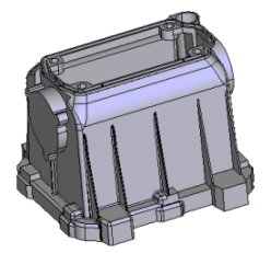 |
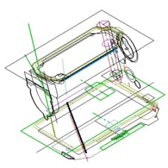 |
On the left side is a complex casting part and, on the right side, its profiles. The user didn't take care of Work Plane history and Profile constraints, so, to modify the casting part and get the expected changes, he/she will have to re-assign the Work Planes and the constraints.