As a prerequisite to understand the content of this document, please read:
This article describes the following:
As you know, not only the Work Plane can be placed on faces, aligned to an axis, but it can be also rotated by n degrees, or just moved as it is from one "linked" position to another "linked" position. In this case what really matters is the "previous" position of the Work Plane. See the following example:

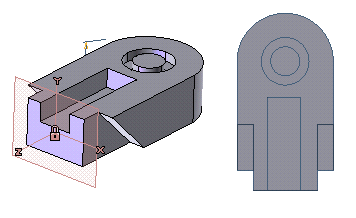
Referring to the left image, a simple solid where the "hidden" history of the Work Plane placements might be like this: we positioned the Work Plane on the face of a solid (the highlighted one), we made a slot and moved the Work Plane, as is, to the center of the Arc on the top face. We finally created a rotational slot.
Referring to the right image, notice that the main solid doesn't have a draft angle.
Now, what happens when re-defining the Linear Solid, and inserting a draft angle to the initial linear sweep? Note that if you re-define a feature, this will be "inserted" into the history, and not "added" as the latest event.
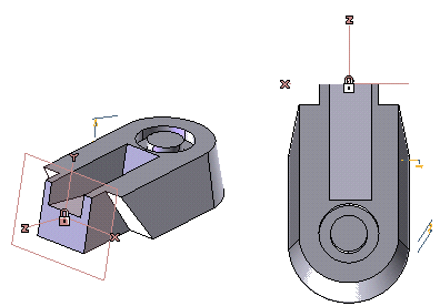
As you can see, the original Work Plane has been rotated by 10 degrees, because it was lying on the original vertical face of the solid. Then, the slot looks perpendicular to the drafted face and moreover, the rotational cutout looks strange. Why? — Because we had originally positioned the Work Plane on the highlighted face.
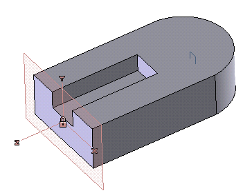
Then we have moved it to the center of the Arc of the top face and we sketched a profile to cut with a revolved cutout.
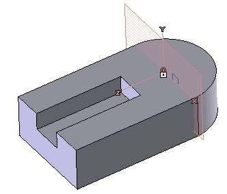
Now, thinking about the Work Plane that we have used to create the revolved cutout, what's the previous Work Plane? It's a "parallel" Work Plane.
The rule is: the previous Work Plane will drive the following one and so on, Therefore, changing the draft angle of the initial linear sweep we have changed the angle to the Work Plane that was laying on one of its faces (the one where we made the blind slot) and we have "modified" all the following Work Planes.
Keeping this rule in mind, what happens with the slot on the side?
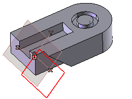
The slot has been created using a cutting profile. The Work Plane that has been used has been moved from the previous position (center of the revolved cutout) and then it had been rotated by 45 degrees about the X-axis.

So, again, changing the angle of the original linear sweep, we'll keep 45 degrees between the two latest Work Planes, but the through slot won't have the requested 45 degrees with the bottom line of the solid.
Notice that, if we had added the draft angle instead of re-defining the initial linear sweep, everything would have worked fine because we wouldn't have changed the history, but would have ADDED a feature at end of the history, without touching the previous events.
Anyway, even in a model like that, you could "repair" it. See How to fix a parametric model by reassigning the Work Plane position to profiles.
But, what had to be the Work Plane history? Theoretically the user could always change the Work Plane history, so even mistakes can be fixed, but, applying the rule from the beginning (the previous Work Plane will drive the following one and so on), will avoid unexpected modifications of your model.
Tip: Always use the same references for the Work Plane (as an example, a template file with Datum Planes and profiles as selectable axes).
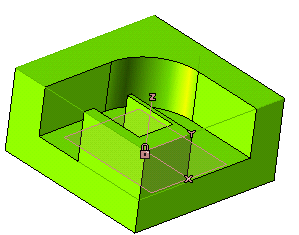
This is a typical way to place the Work Plane. Working in this way without being aware of what The "Work Plane on face" does, you might have some problems after changing dimensions or the shape of your 3D model. See the following example:
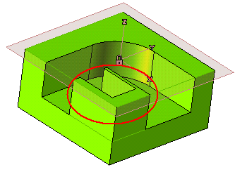
Once you have positioned the Work Plane on the highlighted face, the program has automatically chosen the U=V=0.5 point (sort of a "center") of the surface as point to snap to, and the U direction of the untrimmed surface as the X-axis.
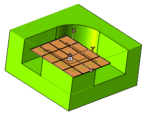
But, editing the model, the original untrimmed surface might be rotated because of editing the initial shape of the solid (even if it's not the same situation of our example) and you might get a different surface, with a different U=V=0.5 point and a different U direction.
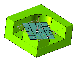
In this case, if you have placed your Work Plane on that face and you've sketched something on it, everything will be moved and/or rotated.
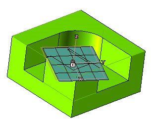
So, coming back to mechanical v/s artistic approaches, if you are a "mechanic" and you'd like to modify your model by changing either the dimensions and/or the original shape, we recommended the follow kinds of Work Plane placements:
