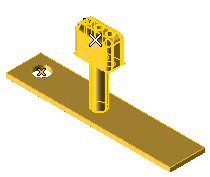
If you click within the drawing/model other than on an entity and drag the cursor, the think3 application goes into automatic window selection mode.
The set of handles is displayed (for details on the handles, see the description of the Move/Copy Entities command).
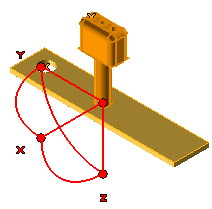
End selection by right-clicking and selecting Continue in the context menu. To change the selected entities, right-click on Entities, select Reset in the context menu and perform selection again.
| Default position of the origin By default, the position of the origin depends on the selected entities.
|
To define a different starting point, you can choose one of the following methods:
- Double-click on the handle and specify the new starting point
- Click on Handle Origin in the selection list to expand it, click on Start point and then specify the new starting point
- Click on Handle Origin in the selection list to expand it, right-click on Start point, select Reset in the context menu and then specify the new starting point.
- Clicking on the central handle and then specifying the end point of the translation.
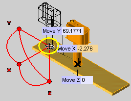
- Dragging the origin or typing the translation values into the Move X/Y/Z boxes, which show up when you pick the handle.
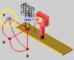
- Dragging the handles at the end points or by typing the X, Y, Z components of the translation into the
Delta X,
Delta Y
,
Delta Z boxes, which show up when you pick the handle.
- Clicking More Options to expand it. As soon as you do, a square handle is displayed on each of the three lines representing the X, Y, Z directions. You can move the selected entities on a plane by dragging the square handles:
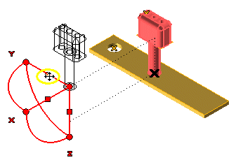
- The square handle on the X axis moves the selected entities on the plane YZ
- The square handle on the Y axis moves the selected entities on the plane XZ
- The square handle on the Z axis moves the selected entities on the plane XY.
To change the selected end point, you can choose one of the following methods:
- Click on the handle and specify the new end point
- Click on Handle Origin in the selection list to expand it, click on End point and then specify the new end point
- Click on Handle Origin in the selection list to expand it, right-click on End point, select Reset in the context menu and then specify the new end point.
To undo the transformation you can check in the preview, before actually applying it and quitting the command, click the  button.
The X,Y and Z X and Y axes are initially parallel to the corresponding Work Plane coordinate system axes. To modify the initial orientation of the axes, you can choose one of the following methods:
- Double-click on an axis and then click on a line you want to re-align it to.
- Select Start Axis Alignment to expand it. In the X/Y
/Z Axis drop-down lists, select:
Line to align the axis to a line. Select the line. 2 points to align the axis to the direction identified by the two points. Select the two points. End point to align the axis so that its second endpoint coincides with a point. Select the point.
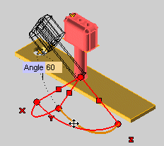
- Drag the arc handle corresponding to the rotation you want to apply (about X, Y or Z). Alternatively, you can click on the handle
corresponding to the rotation you want to apply. An
Angle box will show up as soon as you pick the handle: type the angle of rotation into the
Angle box.
- Click on an axis and then on a line to re-align the axis to the selected line.
- In the X/Y/Z Axis, drop-down lists of
End Axis Alignment, select:
Retrieve Transformation to align the axis to a line. Select the line. Reset Start Handle Position to align the axis to the direction identified by the two points. Select the two points. End point to align the axis so that its second endpoint coincides with a point. Select the point.
To undo the transformation you can check in the preview, before actually applying it and quitting the command, click the  button.
Click on More Options to expand it — you are enabled to apply geometric transformations to entities in the model/drawing.
 or
or  to confirm your selections and apply the transformation.
Click
  to discard your changes.