

Insert Profile
 Symmetry
The Symmetry constraint command enables you to constrain two sets of entities in a 2D profile so that they are symmetric to each other with respect to a symmetry axis.
The Symmetry constraint requires that the entities be input as 3 groups — First Group, Second Group and the Axis Line. So when you apply the constraint you are making the first group of entities to be symmetric to the second group with the symmetry axis being the Axis Line. You can select more than one entity for a group. The program adds the  identifier for symmetric entities.
| Note You must make sure to select equal number and similar entities for both the groups. For example, if you select 2 circles and a line for the first group you will have to select another 2 circles and a different line as the second group entities. In fact, the individual entities of each set are constrained to have the same length/radii. |
Click here to try these simple steps for a quick introduction to the command.
| Note In the profile mode if you use the Edit  Mirror command with Copy option selected, the Symmetry constraint will be applied automatically to those entities. Mirror command with Copy option selected, the Symmetry constraint will be applied automatically to those entities. |
When you select an entity for the Symmetry constraint, the command gives a visual feedback of the selected entities by marking them with consecutive numbers, while an arrowhead shows the sense of direction of the starting entity. The entities with same numbers on both the groups will be made symmetric to each other following the “sense” of the symmetry given by the arrowhead.
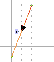
An arrowhead is shown for the entity based on the direction it was created. For example, if you draw a line from top of the screen towards bottom, the arrowhead will also be pointing downwards.

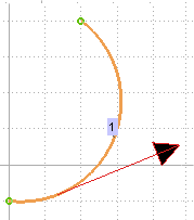
Similarly for an arc, the arrowhead will represent the sense of rotation —from where to where the arc is drawn. In the following image the arc was drawn from bottom to top.

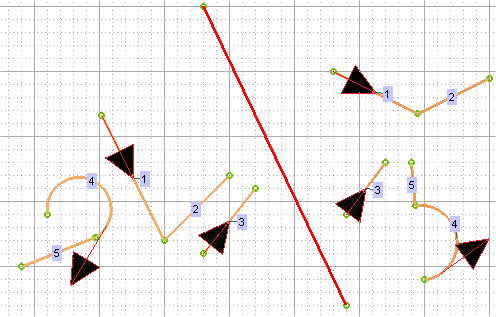
When a set of entities is selected, only one arrowhead is displayed for each "connected" entities. This is explained in the following image. Note that each connected entities on each groups (on the left and right side of the red line, the axis) has only one arrowhead. This is true even for an arc and line connected to each other (entities marked 5 and 4). Independent entities have their own arrowheads (entity 3 on both groups).

You can invert the default sense of the entity by double-clicking on the arrowhead for the entity. Click here to try these simple steps that explain the behavior of the "sense" of symmetry.