The think3 application's Profile environment make it easy to create profile. You can use the 2D Profile or 3D Profile environment to create the respective profiles as per your need. Click here to know about the various entities you can create in the Profile environment.
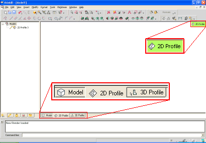
To switch the environment, select the 2D Profile or the 3D Profile tabs present in the bottom-left corner of the Graphics Area. The visibility of these tabs is controlled by the Show tabs Model, 2D Profile and 3D Profile check box present under Next model document area of General - Advanced category in System Options.
Once you have selected a tab, the respective profile environment is activated. This is highlighted by the corresponding icon displayed at the top-right corner of the graphics area.

To switch back to the Model environment you can do one of the following:
 Profile
 Switch to Model.
In both the profile environment you can make use of the static grid, whose nodes can be used as a reference to help you enter points with the mouse. Display of the grid is controlled by the View Grid
Grid Static command. You can also set the background color of your choice; to change the background color, select
Colors and Materials to display the
Colors and Materials dialog box and then change the
Alt. background color under
Environment colors.
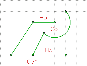
When a Profile environment is active, you can draw a profile using any of the program's commands for inserting and editing geometrical entities. Geometric constraints are automatically added to the profile. When you create a new entity in the profile mode, it is drawn with clearly marked end points. This is true for any entity that you sketch, be it lines or curves.

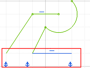
The end points also denote that these entities have some degree of freedom — that is you can drag or move them. When the end points disappear, it means that those entities can no longer be moved. For example, this will happen when a Ground constraint is applied, as shown in the image below.

Also, there are different colors in profile mode indicating the geometry status. These are:
| Well defined entities | : | All relevant constraints are satisfied and all of degrees of freedom have been taken up by the constraints and dimensions. | |
| Under defined entities | : | All relevant constraints are satisfied but there are still some degrees of freedom remaining. | |
| Over defined entities | : | They cannot be solved because there are too many dimensions or constraints acting on the profile for the degrees of freedom available. | |
| Non consistent entities | : | The entities that cannot be solved because no solution exists for the current dimensioning scheme. |
After creating the profile, you can apply dimensional and additional geometric constraints, using other commands available in the Profile environment. You can also automatically apply other constraints by using the AutoConstraint command (only for 2D profiles).
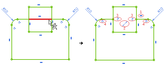
As you draw and edit the profile, the program automatically assigns certain constraints (both to profile entities and to external entities):

There are several other ways to create profiles. After creating a set of co-planar entities, you can convert them to a profile by doing any of the following:
You can also create a 2D profile by simply creating a set of co-planar entities and then applying a linear sweep or revolving the entities.
Note that when you create a profile using any of these methods, geometrical constraints are not automatically assigned. You can assign constraints later, however. Also note that a profile can have reference curves and external entities assigned to it.