Profile environment: Tips and Tricks
Selection sequence
In many commands of the profile environment, you will come across an option to select the Sequence inside the selection list for the command.

In such situations, you can select Single or
Multiple based on the
Sequence that you require the command to apply on.
Multiple — the command acts upon the first two entities that you specify, and then continues with the same action for the successive entities that you specify, using the previous entity as the start point. This sequence continues until you end the command.
Single — the command acts upon any first two entities that you specify. You can then make the command act upon another pair by specifying another pair of entities.
For example, consider the constraint:
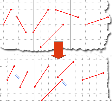
Single
When this option is selected, the lines are made parallel to each other in pairs:

|
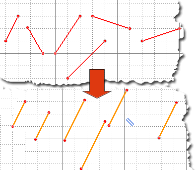
Multiple
When this option is selected, all the successive lines that are selected are made parallel to the first selected line.
You can even use window selection for Multiple sequence selections.

|
Constraint highlighting
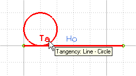
Each constraint has its own unique identifier, which is displayed near the constrained entity. For example, the Ta identifier placed adjacent to a point of tangency. Placing the mouse cursor on the identifiers will highlight the related constrained entities. Also a tool tip is shown, describing the constraints and the type of entities involved. For example, consider the following image, which describes the situation when a circle is constrained to a line using the constraint.

Note that the tool tip is displayed only when the
Enable graphic area tooltips check box is selected in the
Input category of the
System Options. If you want to know more, the program provides the following commands for displaying information about a profile:
- To display information about a constraint, use the
command.
- To check for under constrained, over constrained, and inconsistent profiles, use the Check Profile command.
- To check the degrees of freedom for all the under constrained profiles in the model, use the command.
- To display external entities used to constrain the profile, use the
command.
- To display information about dangling references inside the profile, use the
command.
External entity management
Inside the profile environment you can always reference external entities, if required. If such references to external entities are over constrained but consistent, an appropriate warning is displayed. You can then decide to proceed either by correcting the over defined profile or proceed with the warning.
Note that if constraints are over defined and not consistent, the profile evaluation will fail. The behavior for the over defined profiles inside the profile environment can be decided based on System Options as any one of
Forbidden,
Ask user, or
Allowed, as described
here.
Consider the following example:
- In the 2D Profile environment create a rectangle and exit from the profile mode. Click anywhere on the graphic area to cancel the selection of the rectangle. We will keep this as our external reference (if you wish, you can also extrude the rectangle to solid, for better understanding).
- Again go to the profile mode and create another rectangle. Note that some constraints like horizontal and vertical to the sides of the rectangle are automatically applied. Our aim is to constrain this rectangle to the external entity — the rectangle — created in the step 1.
- Constrain a side of the second profile to be parallel to the first profile by adding the appropriate parallel constraint. Note that this will create an over defined situation. The reason being the fact that the sides are automatically applied the horizontal and vertical constraints. So the parallel constraint to the external rectangle will create an over constrained situation.
- A warning button with caption 2D Profile: it could become overdefined is created at the top right corner of the graphic area. When you click this button, the inconsistent element is highlighted. Note that this button acts as a toggle — clicking it again hides the warnings.
- You can exit from the profile environment with this warning on. The over constrained profile will be marked with a warning symbol in the Model Structure.

This will help you to come back to this profile later on and fix the over constrained issue.
Related Topics


