

Insert MoldDesign
 Cooling
The Mold Cooling command enables you to create a cooling network, perform checks and insert standard parts in the cooling network.
Cooling is one of the most important aspect of MoldDesign. A cooling system is used to dissipate heat and cool the mold quickly and uniformly. Quick cooling is required to obtain economic production and uniform cooling is necessary to maintain a quality product. So an optimum cooling system is the one which achieves both these requirements.
The cooling network is defined by the cooling path, which is defined by a line passing through different mold plates. The path can be constructed using a
2D or
3D profile.
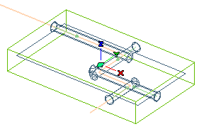
The Path selector is used to select the cooling path. Once the path is selected the preview of the cooling network on the selected path is visible, as shown in the image below.

The Checks node in the selection list enables you to optionally determine the correctness of the cooling network design. The checks highlight the possible errors in the cooling network and can be optionally done for Interference and Drill Length. Click here for details
The Information on Hole dialog box gives you detailed information about each drill hole done of the cooling system. This dialog box is displayed when you select the
Information on Hole node in the selection list. Click here for details.
Also a list of catalogs will be available under More Options in the selection list where you can optionally insert standard parts such as
Plug,
Nipple and
O-Ring into the cooling system. Click here for details.
The Clearance drop-down list under More Options allows you to define how to choose the components in which cooling holes should be created.