Information on Hole
The Information on Hole dialog box provides detailed information about each drill hole created in the cooling network. This dialog box is displayed when you select the Information on Hole in selection list. The cooling channel or the hole through which the coolant passes is referred as drill hole in this document.
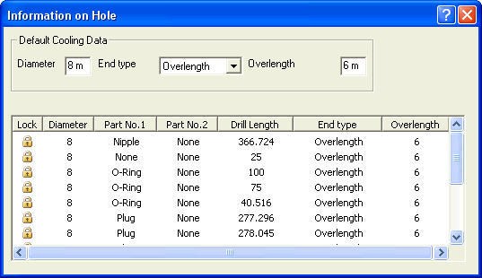
Under the Default Cooling Data area, the default settings for parameters such as Diameter, End type and Overlength are specified. These default values are taken into consideration for all the drill holes created in the cooling network.
| Diameter |
It is the diameter of the drill hole and the values can be entered in the corresponding text box. |
| End type |
It defines the type of intersection of two drill holes. You can select either Overlength or Intersection. |
| Overlength |
It is the length of extension after the intersection. This option is available only if the Overlength is selected as the End type. Enter the length value in the corresponding text box. |
The following are the details available in the table.
| Lock |
The lock is to prevent the user from editing the parameters of the drill hole. A single click on the lock symbol will unlock the lock and enable the user to edit to the required specification. |
| Part No.1 |
It displays the standard part that has been inserted at the starting point of the drill hole. |
| Part No.2 |
It displays the standard part that has been inserted at the end point of the drill hole. |
| Drill Length |
It is the total length of the drill hole is displayed. |
In the preview of the cooling network, each drill hole is represented by an arrow (color of the arrow as per the settings). The arrow indicates the direction of the drill and the following operations can be performed.
-
When this arrow is selected, then the corresponding details of that drill hole are highlighted in the Information on Hole dialog box.
- When you select a row in the dialog box, then the corresponding arrow in the model is highlighted.
- Also you can flip the direction of the drill hole by double-clicking on the arrow in the model.
The Diameter and Overlength parameters can be edited in the Information on Hole dialog box. Following are the steps to be followed for editing.
- First unlock the lock by a single click on its symbol. The Diameter and Overlength of the drill hole can be edited by entering the values in the corresponding text box.
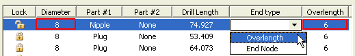
- Also the End type can be changed to either Overlength or Intersection.
Note
A single click again on the lock symbol will lock the drill hole from editing and the default values are restored again. |
Related Topics