


Tools Info
Info Analysis
 Local
Local
Local information about curves, surfaces and meshes can be obtained using the Local command. The command enables you to analyze the curvature of a curve, a surface or a mesh, so as to calculate all the curvature data at the point on which you select it. You can get a very detailed information at the selected location. This command can be applied to entities both in models and drawings.
| Note
When you start the Local command the program prompts you to select a shape. This can be a curve, a surface, a face of solid, a mesh or any entity whose local information you wish to extract. |
When you select an entity, except a mesh, at the selected point a red circular marker appears. This marker can be dragged along the selected entity. Along with the marker the parameters U and V are parameter U is displayed with their valuesits value at the point. You can also display information about other points on the selected entity by typing the parameter values for the new points in the corresponding mini-dialog boxes for U and V. Note that for drawings only the parameter U will be available.
When the selected entity is a mesh:
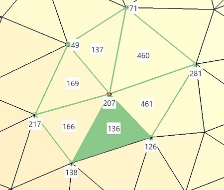
Under these check-boxes, a node or facet selector allows you to access directly to the node or facet you wish to display information on. Another way to access a specific node or facet is to navigate forward and backward among the nodes or facets using the arrows of the common ThinkDesign navigator.
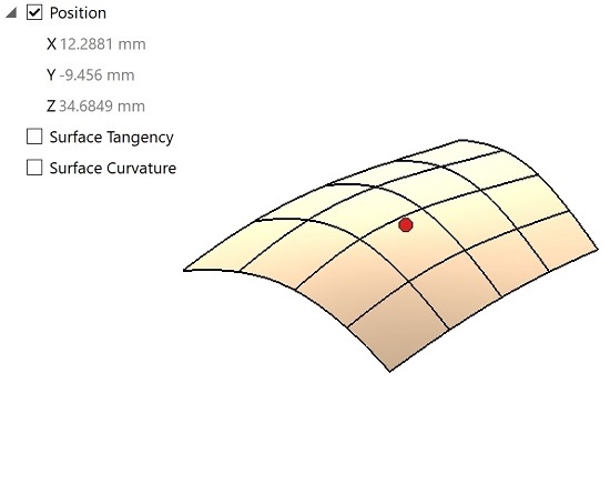
All the required data are displayed in the selection list under categories such as Position, Surface Tangency, Surface Curvature, Curve Curvature and so on depending upon the entity selected. Use the check-boxes against each category in the selection list as a toggle for displaying information grouped under that particular category. In the selection list the information can be viewed or hidden respectively by expanding or collapsing the corresponding node.
Depending upon the entity you have selected, the following details can be displayed:
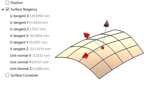
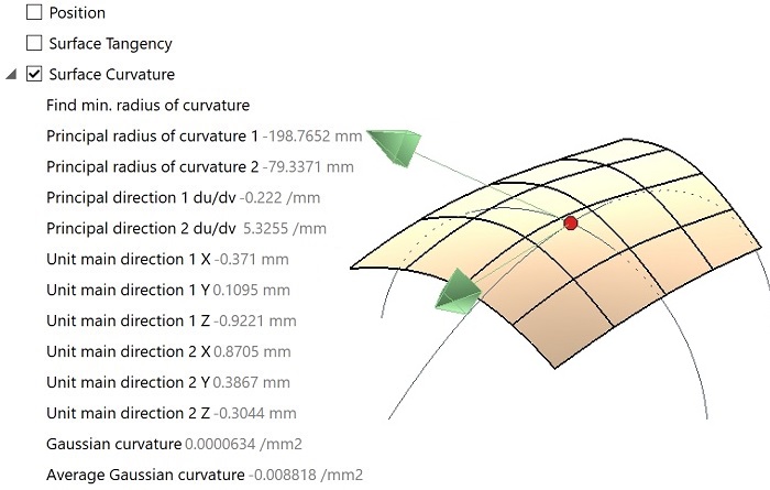
In the following illustrations you can see the output data you will obtain if you check respectively the Position,
Surface Tangency or
Surface Curvature boxes.
 |
 |
 |
When the selected entity is a mesh, the Hide minidialogs check-box allows you to control the
visibility of the mini-dialog boxes displayed by the command, in particular the ones related to the topological information.
| Incident facets and connected nodes of node 207 | Nodes and adjacent facets of facet 136 |
 |
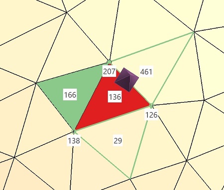 |
A very useful feature is that, geometric data — such as points or arcs — can be added to the model by selecting the Insert Geometric Data check-box.
Consider that you need to retain a point obtained after the local analysis — simply select the Insert Geometric Data check-box and apply.
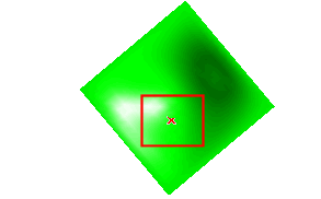
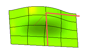
In the case you are checking the Surface Tangency, you can easily create lines corresponding to the tangents and the normals in both the parametric directions U and V (and binormal in case of curves).
In the case of the Surface Curvature, you can create the arcs representing the two main curvatures of the surface and the main directions at the selected point.
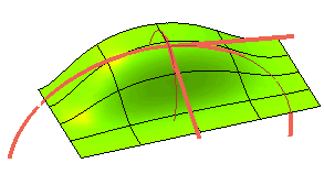
All of these entities can profitably be used as design aids.
Please note that when the selected entity is a curve of the Curve on Surface type, a specific option enables you to select whether to display data for the curve itself or for its base surface, which can be very useful in a number of situations.