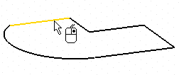
As soon as a curve is selected, the preview of the corresponding surface is displayed

Each time you modify a parameter, the preview is also updated.
To change the selected curves, right-click on Curves in the selection list, select Reset in the context menu and perform selection again.
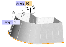
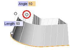 .
.| Length | Applies a constant length along the sweep direction. In the Length mini-dialog box, type the length of the path, or drag the two circular handles at the end points of the path to interactively set the path length. 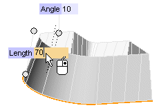 See "Continuity at transitions" for further details on what happens when using the Length mode if some base curves are not planar. |
| Height | The height of the path along the sweep direction. When the base curves are not plane, the height value is computed starting from an "average plane". In the Height mini-dialog box, type the height of the path, or drag the two circular handles at the end points of the path to interactively set the path height. If the base curves are plane the Height and the Length options work exactly the same way. To better appreciate the different behaviors of the Height and Length options, see "Comparison between the Length and the Height mode". |
| From-To | To define the path through an initial and a final surface. Click From and select the surfaces you want to start from (if the base curves are planar, their plane is the default starting surface), then click
To and select the surfaces you want to end at. To avoid undesired results when you select the From-To option, make sure that the projection of the base curves onto the ending surface in the sweep direction is "contained" in the surface itself. |
- Define how to manage transitions — that is: edges between adjacent curves in the base curve set
- Choose whether to create the base surfaces (endcaps) (only if the base curve is closed)
 or
or  to confirm your selections and create the surfaces.
 to discard your changes.
