

Insert Sheet Metal
 Wizard
The Sheet Metal Wizard command enables you to create multiple sheet metal components starting from a single solid (with or without sheet metal attributes). The sheet metal property can be separately specified for each component that is being created.
The process of converting a single solid into a sheet metal component involves primarily three steps:
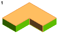
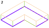
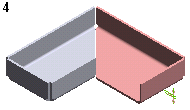
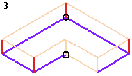
The Sheet Metal Wizard command single handedly takes care of all the three operations. The command's selection list has various options and selectors to execute the required operations. The command execution process is composed primarily of the following steps (same has been graphically explained in the succeeding images).
 |
 |
 |
 |
||
 |
 |
 |
The selection of edges for creating bends or rips is done in groups and for each group you can assign independent local properties. By right-clicking on a group (either Bend Group or Rip Group), the following options are displayed:

Once multiple groups are created, the group navigation buttons  get activated. They are used for:
Once all the selections are made, the preview of the components can be viewed by selecting the Show Preview ( ) button. At this stage the Resulting Components options is also displayed in the selecting list. In case the selection of rip locations is such that two or more resulting parts are being created, you can specify the Local Properties for each part using this option. Use the navigation buttons
  to set a particular component as current. The preview of the current component is highlighted by a grid over it. This makes it easy to notice the current component in the Graphics Area.
| Note To navigate between multiple groups or components you can either use the navigation buttons or select the corresponding group/component number directly from the drop-down list. |
 |
Additional settings can be made in the Sheet Metal category of Document Properties. The options present here control the visualization of various selections that are made for the selectors of the Sheet Metal Wizard selection list and the resulting sheet metal components.
On failure of the Sheet Metal Wizard command, a warning message gets displayed. The More Details button is available in this warning message. On selecting this button, the warning message expands and displays the sheet metal wizard component number that is causing the failure. Also, in some situations it displays the reason of failure of this command.
| Note To redefine the Sheet Metal Wizard command, right-click on one of the sheet metal components created by the command in the Model Structure and select Sheet Metal Wizard - Redefine Feature from the context menu. To delete the components created by the Sheet Metal Wizard command, right-click on one of the created sheet metal components in the Model Structure and select Sheet Metal Wizard - Delete from the context menu. |