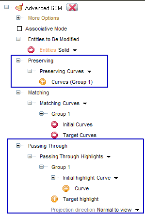
A most useful set of powerful constraints is available in the Advanced GSM command, under the Passing Through node in order to enable you to apply a controlled modification to a shape so as to have it through some specified points, curves and surface boundaries or even highlight lines and silhouettes.

The Passing Through drop-down list enables you to set the following constraints.
This option enables you to constrain a shape through one or more points just by specifying the Projection type:
| Normal | the points will be projected normally onto the surface. |
| Flat | the points will be projected onto the surface using a linear projection along a specified direction. |
| Single curvature | the points will be projected onto the surface using a cylindrical projection for which you will have to specify the axis. |
| Double curvature | the points will be projected onto the surface using a spherical projection for which you will have to specify the center. |
This option enables you to constrain a shape through one or more curves just by specifying the Projection type:
| Normal | the curve will be projected normally onto the surface. |
| Flat | the curve will be projected onto the surface using a linear projection along a specified direction. |
| Single curvature | the curve will be projected onto the surface using a cylindrical projection for which you will have to specify the axis. |
| Double curvature | the curve will be projected onto the surface using a spherical projection for which you will have to specify the center. |
This option enables you to constrain a shape through one or more highlight lines. This method can be particularly useful, as it enables you to proceed as follows:
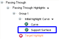
This option enables you to constrain the model, or part of it, through a curve obtained as a section of the model itself — which can be created using the
Insert Free Hand Curve command.
Please note that with this method the starting curves are automatically selected by the program.
| Design Review Using the Passing Through Section constraint enables you to very quickly accomplish your design review:
|
The Passing Through Silhouette option enables you to modify the silhouette of a shape.
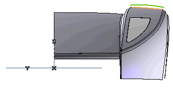
In the following illustration, the orange curve is a part of the silhouette of the model relative to the view along the X axis. The green curve is the target silhouette to be reached (for example, you might have created it using the
Insert Free Hand Curve sketching tool).
| Note
Please take into account that if the entities to be modified are a big number, the computation time can grow considerably. In addition, the computed silhouette can have some discontinuities or can be multiple for a single direction. |
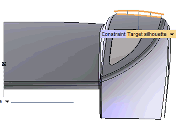
| Target silhouette | To constrain the initial silhouette to match the selected target one. |
| Free | No constraints. |
| Normal | The initial silhouette will be projected orthogonally onto the target. |
| Flat | The initial silhouette will be projected using a linear projection along a specified direction (to be chosen in the Direction drop-down list below). |
| Double curvature | The initial silhouette be projected using a spherical projection for which you will have to specify the center. |
| Single curvature | The initial silhouette will be projected using a cylindrical projection for which you will have to specify the axis, using the Axis drop-down list below. |
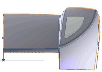
The Silhouette option has also been added to the
Preserving drop-down list, so as to enable you to preserve silhouette curves from the modification.
Also in the preserving case, two methods are available in the Silhouette type drop-down list:
Curve and
Direction, and the meaning is the same.
In the following illustration, the silhouette curve to be preserved is the orange curve, the same used in the previous example as the initial silhouette.
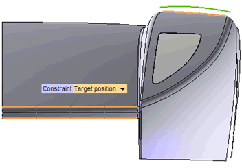
and the result is the following.
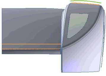
As you can see, the silhouette curve has been preserved successfully.