Applying a through highlights controlled modification
In this job you will apply a controlled modification to the shape of some surfaces so as to have one of their highlight lines match a specified curve, in order to obtain an improved shape.
The steps you will follow are the following:
- Step 1:
Display zebra lines on the surfaces.
- Step 2:
Create the "highlight" line by using the Silhouette command.
- Step 3:
Based on the actual highlight line, create a smoother curve by using the Insert Curve Through Control Points command.
- Step 4:
Constrain the surfaces to have their new highlight line coincide with the smoother curve you created by using the Passing Through option of the
Advanced GSM command.
This method guarantees that you will actually obtain nicer and smoother surfaces.
Step 1: Display zebra lines on the surfaces
- Open file "GSMH.e3".
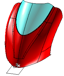
- Run Tools
 Info
Info Zebra
Zebra
- Set the Type to Isophotes.
- Set the Isophote Direction to Z.
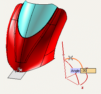
- Click on the handle corresponding to the XY angle. In the Angle mini-dialog box, type -30.
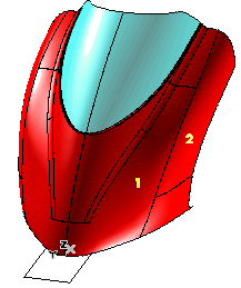
- Select the two surfaces as in the following illustration.
Isophotes will be immediately displayed:
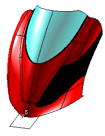
The highlight line you will create is the one pointed at by the blue arrows in the following image.
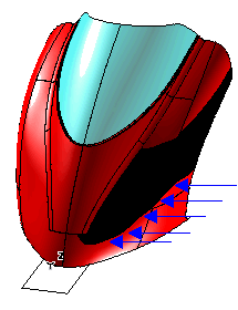
In the following step, you will create the curve corresponding to the above highlight line by using the Silhouette command.
Step 2: Create the highlight line
- Start the Silhouette command.
- Select the surfaces in the right half of the model.
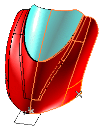
- Select the Interactive direction check box and set the Direction to Z.
- Click on the handle corresponding to the XY angle. In the Angle mini-dialog box, type -30.
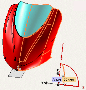
- The silhouette curve is created. As you can see it's not particularly smooth.
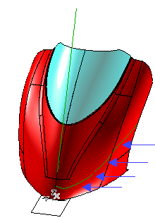
In next step, using the Insert Curve Through Control Points command, you will create a smoother curve.
Step 3: Create a smoother highlight line
- Start the Insert Curve Through Control Points.
- Specify the five points as indicated in the following illustration, where the first and the fifth point coincide respectively with the first and the last endpoint of the highlight curve.
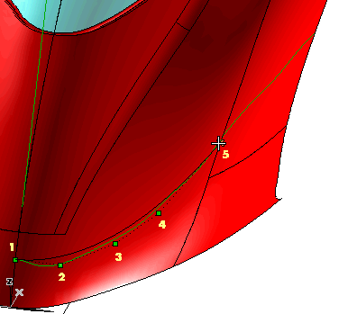
The curve is created.
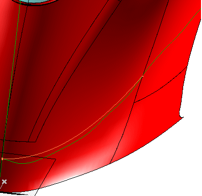
In the following step, you will use the Advanced GSM command to constrain the surfaces to have a new highlight curve coincident with the smoother curve you created.
Step 4: Apply the through highlights controlled modification
- Start the Advanced GSM command.
- Set Preserving to Curves and click on Curves (Group 1). Then click on the top boundaries of the surfaces in the right-hand half of the model.
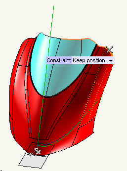
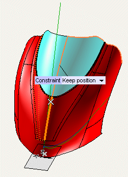
- Click on Curves (Group 2). Then select the surface boundaries on the symmetry plane of the model, as in the following illustration.
- Under Passing Through, set the
Passing Through drop-down list to
Highlights.
- Set Initial highlight to
Curve and click on the highlight curve obtained in Step 2.
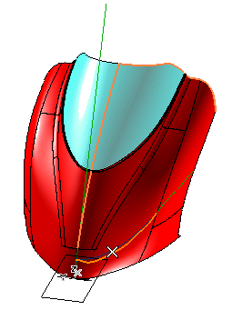
- The Support Surface item shows up in the selection list to warn you need to select the surface the initial highlight refers to.
Selecting of the Support Surface
Please note that if the highlight curve you select is of the Curve on Surface type, no support surface selection is required, as the surface is autoamtically identified by the selected curve. |
Click on the support surface:
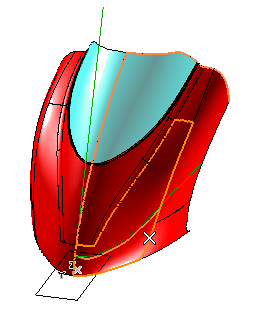
Click on the surface the highlight curve you selected refers to.
- Click on Target highlight and select the smoother curve you created in Step 3.
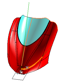
- Set Projection direction to
Normal to view.
- Select the surfaces to be modified.
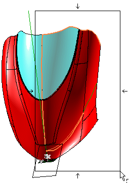
Here is the preview of the result.
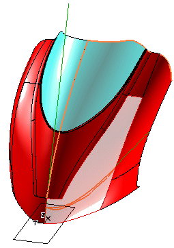
- Click
 to confirm the modification and stop the command.
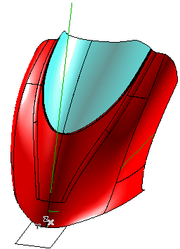
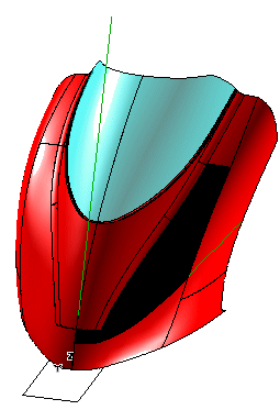
- You can now check that the modified shape is really through the highlight line you created in Step 3. To do this, repeat the same operations you did in Step 1
- Run Tools
 Info
Info Zebra
Zebra
- Set the Type to Isophotes.
- Set the Isophote Direction to Z.
- Click on the handle corresponding to the XY angle. In the Angle mini-dialog box, type -30.
You will see that the zebra line visualization you get matches exaclty the line you created in Step 3.

 Info
Info Zebra
Zebra


 Info
Info Zebra
Zebra


 to confirm the modification and stop the command.
 Info
Info Zebra
Zebra