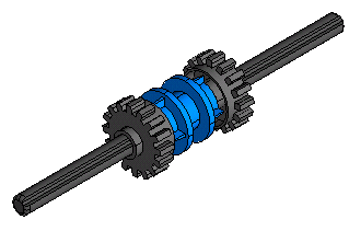
Suppose you wish to check interferences among some parts of the assembly shown in the following illustration

The model related to this job is check_interferences.e3, available in the samples folder.
After starting the Check Interferences command, proceed as follows:
| 1 | Select the first group of components.
The selection list updates as shown.
|
|||||||||||||||
| 2 | You can now add one or more parts to the group of components/solids currently selected (Group 1) or select Group 2 and add the next part(s) to this group. Suppose you choose this last possibility and select the driving ring.
The selection list updates as shown, that is another line is created to select an additional component/solid group, if required and the Check mode option is displayed.
The Check mode option enables you to define the interference check modality by selecting one of the following options in the drop-down list:
See Checking interferences among or inside groups for more information. |
|||||||||||||||
| 3 | Suppose you've ended your selection and require the interference check. Click  (Compute). The solids/components involved in the interference are highlighted. The highlight of the interferring parts is based on the kind of selection filter that is set (Components if the filter is set to Component, Solids if set to Solid. Also you can activate selection of solids inside components). (Compute). The solids/components involved in the interference are highlighted. The highlight of the interferring parts is based on the kind of selection filter that is set (Components if the filter is set to Component, Solids if set to Solid. Also you can activate selection of solids inside components).
Also a dialog box with the results is displayed. This dialog box includes two tabs, By Entities and By Interferences, which show the tree views of the interference results, grouped by entities/interferences. Expanding the tree, more information can be retrieved. When you select an item in the tree views, all colliding faces of the selected objects in the Graphics Area are displayed depending upon Display option.
The dialog box also includes the following options/buttons:
See Creating interference solids and Creating Visual Bookmarks showing interferences for more information. If you wish to introduce a tolerance value, you can enter it from the Minimum Distance option (available when expanding More Options), enabling you to set a minimum distance between the objects so that when their distance is less than this value the objects are considered to be colliding. Requiring a complete analysis, you may have it done for you just selecting all components. If the analysis of the components that you selected hasn't detected any interferences, a message is displayed. Note that, when you start the Check Interferences command, the selection filter for entity types is automatically set to solids and components and you can choose an additional filter, allowing you to consider components inside the selected component(s)/solids inside the selected solid(s). By performing Selection Filter and selecting the Component option under Inside in the dialog box, when you select a component/solid, all the nested components/solids are actually selected. If the option is not selected, when you select a component/solid, only the component/solid at the current level is actually selected. |
|||||||||||||||
| 4 | Click  (Cancel) to discard your changes and quit the command. (Cancel) to discard your changes and quit the command.
Note that by performing again the command, the selection list displays
|