Grid Characteristics
The grid is an array of equally spaced nodes that are arranged in an orthographic manner. The grid acts as a mode of reference; when the grid is visible, every point specified using the mouse automatically snaps to the nearest grid node. The grid also provides a sense of scale of the model.
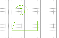
The Grid nodes are positioned at the intersection of Grid lines, which can be continuous or dotted as shown below.

Grid terminology
- Step: : It is the minimum distance between the nodes
- Major line : These are the continuous lines in the grid
- Major line subdivisions: : It is number of divisions present between the subsequent Major lines (by the dotted lines)
The display of the grid is turned ON or OFF by using the Static Grid and
Grid Off commands.
There are two types of Grids available in the think3 application:
Both these grids are generalized as Static Grid and can be displayed over the graphics area in all the environment — Model,
2D Profile and
3D Profile.
Standard Grid
The Standard Grid is a normal two-dimensional grid having the following characteristics:
- In the 2D Profile environment, the grid remains parallel to the screen unless you dynamically rotate the view.
- The grid will not be visible under extreme positive and negative magnification (zoom).
- The grid can be rotate only up to a limit, after that it becomes invisible.
- The grid can be individually turned ON or OFF in each environment.
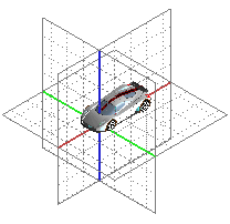
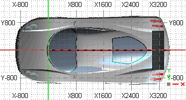
It is an upgraded form of the Standard Grid having many dynamic features. The Reference Grid is displayed as three perpendicular planes, which can be turned ON/OFF singularly. The Reference Grid in different view orientations is shown below.
 |
 |
| Rotated view |
Orthographic orthogonal view |
Note
All the controls for the Reference Grid (including its enabling/disabling) are available in the and its branch categories (
Reference &
Advanced) of the
Document Properties. |
The 3D Reference Grid works differently in the and
modes and for the orthogonal and rotated views. In the Perspective mode, the grid is shown only in the rotated views and the grid labels are never displayed. However, in the Orthographic mode the grid is visible in both the orthogonal and rotated views and in the orthogonal views, the labels are displayed. Note that the Standard and Reference grids cannot be viewed simultaneously. The main characteristics of the Reference Grid are:
Grid orientation
- The grid is initially displayed in the default orthogonal orientations (,
and
).
- The grid can be oriented with the work plane and vice-versa.
- The grid, by default passes through the world origin. However, it is possible to move the grid origin to the current work plane origin.
- The alignment of the grid can be either set to the
World (world X, Y & Z directions) or to the
Current work plane orientation.
Grid visualization
- When the grid is viewed orthogonally, it covers the entire graphics area.
- When viewed from the perspective/rotated angle, the extent of the grid is limited to the bounding box of the scene.
- The percentage extension of the grid can be changed from 100% to 300% with respect to the bounding box limits.
- The Origin axes of the grid are displayed boldly with special color to make them prominent. The visualization of the
Origin axes can be turned ON/OFF.
Grid spacing
- The grid step will be same as that defined for the Static Grid.
- The grid spacing is auto-refinable. It means that while zooming, the minor and major lines automatically adjust their subdivision with respect to the current zoom level.
- The Reference grid is refined as per the values specified for the Step: and
Major line subdivisions: in the
Static grid area for the
Grid category of
Document Properties.
Grid labels
- The text labels with the numeric values of the major lines are displayed on all the four sides of the graphics area.
- The grid labels are visible only when the grid is viewed orthogonally.
- It is possible to customize and turn ON/OFF the display of labels.
Grid snap
- It is possible to enable or disable the Reference Grid snap by using the

 option from the menu bar.
- The snap points are the intersections of the grid lines at the current level of refinement. Hence, when the grid is automatically refined while zooming, the snap is changed to adjust to the new grid steps.
- If the input mode (
 ) is
, the snap on the grid will work only if it is viewed orthogonally.
- If the input mode is , the snap will work only on the active grid plane (displayed in a different color). The active grid plane is that reference plane which shares its origin and orientation with the Work Plane (the Work Plane should not be hidden).
Work Plane alignment
- The Work Plane can be aligned with one of the Reference Grid planes by using the ,
or
commands.
Note
As the Reference Grid is relative to the working area, each component has its own Reference Grid. When a component is set as current in an assembly, the static grid (Standard or Reference) associated to its working area becomes active. |


 Snap
Snap  Reference Grid option from the menu bar.
 Input) is
On View, the snap on the grid will work only if it is viewed orthogonally.