The  Symbolic Mating command enables you to easily define, modify or delete a set of constraints to be used when importing or replacing a part.
You can find this command in the Tools menu of the think3 application. If not present, you may have to create a new toolbar with the Tools  Customize command. The command is not available when the drafting environment is active.
| The symbolic mating environment is enabled only if the current document is a model; the model must contain the parametric template representing the part. |
Symbolic mating constraints can be defined in any moment during the creation of a catalog. It's obviously only after you have defined some symbolic mating constraints for a part that, when positioning that part in the think3 application, you'll have to specify its constraints inside the current model.
Upon execution, the command displays the following dialog box:
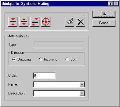
The operations that you are enabled to carry out are:
Defining a symbolic mating constraint
To define a symbolic mating constraint:
| 1 |
First, define the constraint Direction, which can be:
| Outgoing |
the kind of constraint that will be used when components are to be positioned |
| Incoming |
the kind of constraint that will be used when components are to be replaced |
| Both |
the kind of constraint that will be used both when components are to be positioned and when they are to be replaced.
|
|
| 2 |
Define the constraint Type, which can be:
 |
Coincident Aligned |
To create the constraint you have to select a face of the component. When positioning the component, the constrained face will be positioned on the same plane of the face of the model you will select and with the normals pointing in the same sense. |
 |
Coincident Antialigned |
To create the constraint you have to select a face of the component. When positioning the component, the constrained face will be positioned on the same plane of the face of the model you will select but with the normals pointing in opposite sense. |
 |
Parallel |
To create the constraint you have to select a face of the component. When positioning the component, the constrained face will be positioned on a plane parallel to the one of the face of the model you will select and with the normals pointing in the same sense. |
 |
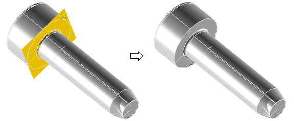
Concentric |
To create the constraint you have to select a face of revolution of the component. When positioning the component, the constrained face will be positioned coaxially aligned to a revolution face you will select in the model.
|
Face highlighting
Note that as soon as you select the constraint, only those faces to which the constraint can be applied will be highlighted. So, if you select a coincidence constraint, only plane faces will be higlighted. On the contrary, if you select the alignment constraint, only faces of revolution will be highlighted. |
|
| 3 |
In the Name box, type the constraint name, or select it in the drop-down list.
Constraint names
Constraint names are very important when replacing components. In fact, when you replace a component, constraints to the model will be retained only if their names are the same both in the old and in the new component. Be careful not to assign the same Name to two or more constraints; it may prevent the Replace Part command from functioning correctly. |
|
| 4 |
In the Order box, type the number corresponding to the order in which you want the constraint to be requested when positioning the component; order number corresponding to different constraints will be sorted in ascending order.
|
| 5 |
In the Description box, type the prompt message that will be displayed when positioning the component, or select it in the drop-down list.
|
| 6 |
Select OK. |
Modifying a constraint
To modify a constraint, proceed as follows:
| 1 |
Select Edit  |
|
|
| 2 |
In the part, select the constraint to be modified. |
| 3 |
Modify the values you need to change (Order, Name, Description)
After modifying a constraint ...
... to end the edit session for that constraint select OK. If you need to modify some more constraints, you needn't select OK, but, before changing the values, you must obviously remember to select the new constraint on the part. |
|
| 4 |
Select OK. |
Deleting a constraint
To delete a constraint, proceed as follows:
| 1 |
Select Delete  |
|
|
| 2 |
Select the constraint to be removed:
The constraint is immediately removed.
|
| 3 |
Select OK. |
Try to...