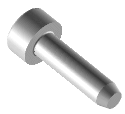
Applying symbolic constraints to a screw
In this example of the usage of the Symbolic Mating command, you have a screws catalog and you need to define the constraints to correctly mount the part in an assembly.
These are the steps necessary to define a shoulder constraint:
- Select the Ougoing option under Direction
- In the Order box, type 0
- In the Name box, select SHOULDER
- In the Description box, select Select the shoulder
- Select the Coincident Antialigned constraint
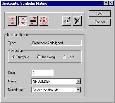
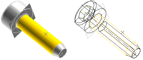
- Click on the bottom surface of the screw head:
the constraint will be marked by the plane surface displayed in the illustration.
- Select OK.
Next, you'll define an outgoing and incoming Concentric constraint for the screw axis.
- Select the Both option under Direction
- In the Order box, type 1
- In the Name box, select AXIS
- In the Description box, select Select the hole
- Select the Concentric constraint
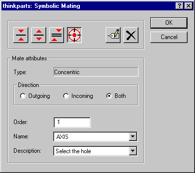
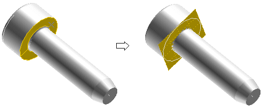
- Click on the cylindric surface of the screw (in the following illustration the component is displayed both shaded and wireframe, so that you can see both the selected surface and the axis of revolution):
- Select OK.