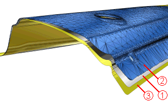
1 is the original CAD data
2 is the measured data
3 is the result of applying compensation on the original data based on the measured data
During sheet metal manufacturing, maintaining design quality throughout the production process is a big challenge. Die stamping sheet metal components and other parts with complex shapes give rise to a problems like spring-back, warping, shrinkage (due the tendency for a metal part to partially return to its original shape after deformation because of the elastic recovery of the material). This results in considerable differences between the digital model and the real (manufactured) part.
Designers try to correct or prevent material problems of this type with various 'compensation' methods. The FEA (Finite Element Analysis) tools are used to simulate and predict what the shape the part will take after spring-back. However, the FEA process is separate from the design process and requires significant time and effort in integrating the results into the modification of the tool design.
The Compensator tools provides solution of these problems through digital compensation. It automates the compensation process, saving time and reducing tedious manual labour. The compensation process maintains the same surface structure (topology) and the quality as of the original surface model. As a result, user interaction is highly reduced and the need to spend time in rebuilding and redrawing compensated surfaces is eliminated.
It is also possible to compensate the part based on the measured data (scanned data of the physical part) rather than on the simulation data that come from the FEA. The deformation data is applied to the digital model employing an inverse law, that is, the functionality applies reverse deformation by reading the deformation from the physical model and applying it to the digital model. The process is fast and enables the quality of CAD data to be maintained. A big additional advantage is that the design changes can be handled in a very effective way. Minor design changes can be applied to the compensation even without making an additional FEM calculation.
As shown in the follwoing example:

1 is the original CAD data
2 is the measured data
3 is the result of applying compensation on the original data based on the measured data