Please note that you can accomplish this task by loading file "OffsetSurface.e3".
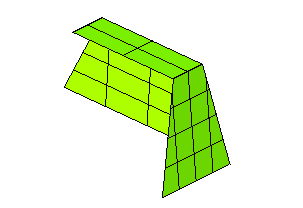
In this job you will apply the Offset Surface command to a set of surfaces both in the
No trim/extension and in the
Automatic trim/extension mode.
Please note that you can accomplish this task by loading file "OffsetSurface.e3".

| 1 | Start the Offset Surface command. Set the
Mode drop-down list to
No trim/extension: with this mode the offset of each selected surface will be created separately and the resulting offset may differ from the original shape. |
| 2 | Set the Reference drop-down list to
Normal (for an explanation of the
View option , see "Using the Reference View option"), so as to create the offset surfaces along the normal of each of the selected surfaces (either on the positive or on the negative side: you can double-click the Distance handle to invert the orientation). Then select the surfaces as in the following illustration.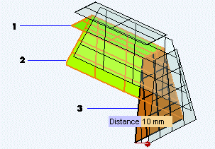 As you can see from the preview, the resulting shape differs from the one of the original set of surfaces you selected. You can define the offset distance by typing its value into the Distance box. |
| 3 | To maintain the shape of the original surfaces, change Mode to
Automatic trim/extension: the initial connection between surfaces will be preserved.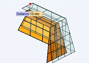 Note that the offset direction along the normal can always be inverted by double clicking on the Distance handle. 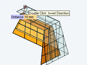 |
| 4 | Click  or or  to confirm your selections and create the surfaces. to confirm your selections and create the surfaces.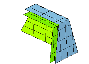 Please note that the result in the case of the No trim/extension mode would be the following: 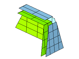 |