Creating a blending shape between two contours

Once you have started the Blending Shapes command, you can proceed as follows (please note that you can follow this step-by-step example by loading file: "BlendingShape.e3").

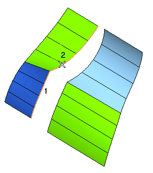
1 Select the curves/surface boundaries identifying the first contour


and end selection by right-clicking and selecting Continue in the context menu (to change the selected contour, right-click, select Reset Current Selection and select a different contour).
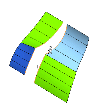
2 Select the curves/surface boundaries identifying the second contour


and end selection by right-clicking and selecting Continue in the context menu (to change the selected contour, right-click, select Reset Current Selection and select a different contour).

How to profitably use the command
Please note the order of the following steps is not important. The command is designed so as to enable you to change the values of the numerous settings as you like and to interactively assess the possible results using the preview mode.


3 Click the preview button ( ) on top of the selection list to display a preview of the blending surfaces.
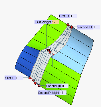


Displaying or hiding mini-dialog boxes
The Hide minidialogs check box is available under More Options to control the visibility of the mini-dialog boxes displayed by the command.
When selected, mini-dialog boxes are not visible.
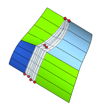


When not selected. mini-dialog boxes are displayed.
Hiding mini-dialog boxes can be very useful especially when working with complex models to simplify visualization.


4 To ensure the same continuity conditions are applied along both contours, the Same continuity check box must be selected and then select the continuity condition you want to apply in the Continuity drop-down list (for example, select Tangent) in the selection list. If you uncheck Same continuity, a separate Continuity drop-down list will show up at each contour, enabling you to set different continuity conditions along the two contours.

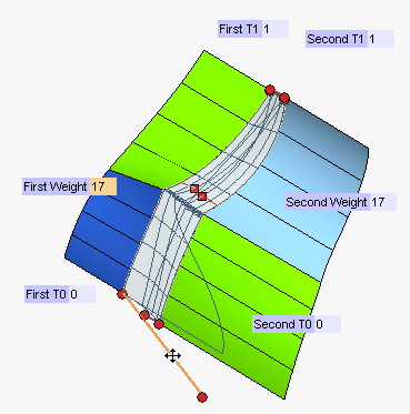
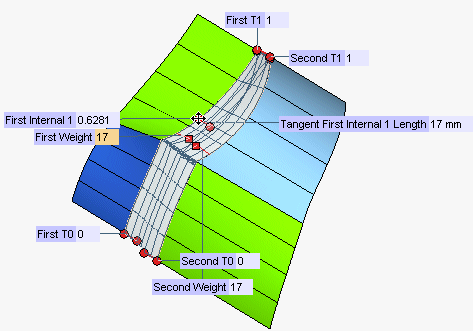
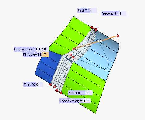
A global numeric value — the weight —  is assigned to each contour to be connected (First Weight, Second Weight). The higher the weight, the higher the influence of the tangent and curvature fields of the corresponding contour on the shape of the resulting surface. A square handle is associated with the weight so as to enable you change it interactively.
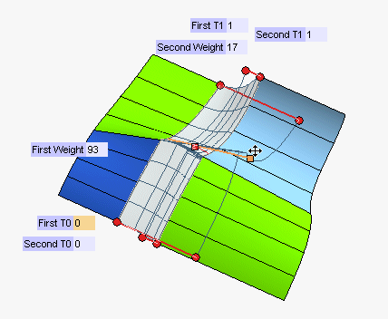


Updating the preview
The Update preview at end drag check box enables you to control the preview update mode. When selected, the preview is updated only when drag operations are over (which can be very useful to speed up operations, especially in case of complex models). When not selected, the preview is updated continually during drag operations.


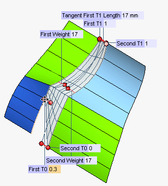
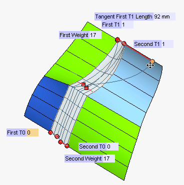
5 You can change the position of the endpoints of both contours by entering the desired values in the First T0, First T1, Second T0, Second T1 boxes or by dragging the corresponding handles:


Displaying the tangency law and the control points
Two check boxes under More Options enable you to set some visualization options: Show tangency law and Show control points.
  • Show tangency law
    • When selected, the curves representing the tangency law for the selected point are displayed.
    • When not selected, the curves are not displayed.
       
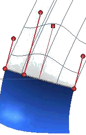
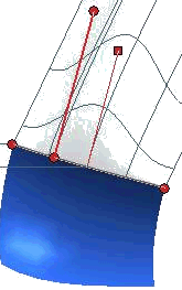
  • Show tangency law NOT selected

    Show tangency law selected


    When the model is a complex one, it can be very useful to be capable of turning the visualization on and off as you like, so as to interactively assess both the tangency law and the resulting shape in the preview.

  • Show control points
    • When selected, the control points of the resulting shapes are displayed.
    • When not selected, the control points are not displayed.

Controlling the tangency section

Appropriate options provide control on the "tangency section" so as to get a better shape along the two contours. As a matter of fact, tangency weights controlling the final shapes are computed along the contours. A set of values is computed along each of the two contours. The Tangent Length Law drop-down list under More Options enables you to choose how the tangency laws are generated from these values:

Fit The given contour values are smoothed using the least square method.
Fixed endpoints & fit The contour values corresponding to the parameter values of 0 and 1 will be retained and kept fixed, while the least square method will be applied to all the remaining contour values.
S-Shape & fit The contour values corresponding to the parameter values of 0 and 1 will be retained and kept fixed, the derivative value is set to 0, while the least square method will be applied to all the remaining contour values.

The Degree box enables you to choose the polynomial fitting method that best matches your need: 1 is linear, 2 parabolic, 3 cubic and so on.

Management of closure points
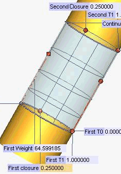
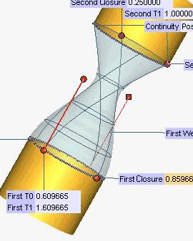
An additional handle (First Closure, Second Closure) is provided when one of the contours is closed, so as to interactively enable you to change the location of the closure point on the contour itself, thus resulting in a further modification of the shape. See the following example for details.

Initially, the closure point is located at the position corresponding to the value 0.5 of the parameter on the contour. By dragging the point, you can modify the shape.


6 Click Undo ( ) to undo the previous changes.

7 You can drag the corresponding handles also to modify the length of the tangent vectors at the endpoints, or specify the desired values in the Tangent First T0 Length, Tangent First T1 Length, Tangent Second T0 Length, Tangent Second T1 Length boxes:


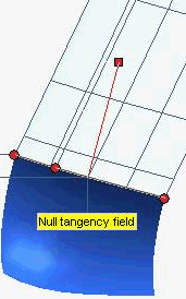
Null tangency field warning
If you modify the length of the tangent vectors along a contour (no matter whether at the end points or at the additional internal points), if all the lengths are null, then the tangency field is null. In this case, a new warning message is displayed.


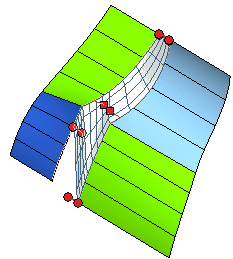
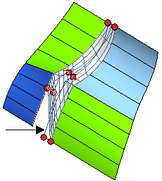
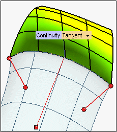
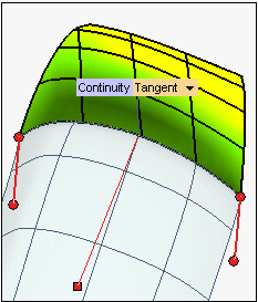
Unless the geometric conditions prevent you from doing so, you can also modify the direction of the tangent vectors. To do this you can rotate the vector while holding the selection button of the mouse down on an intermediate point of the handle between its own endpoints:


Defining the direction of tangent vectors as predefined directions
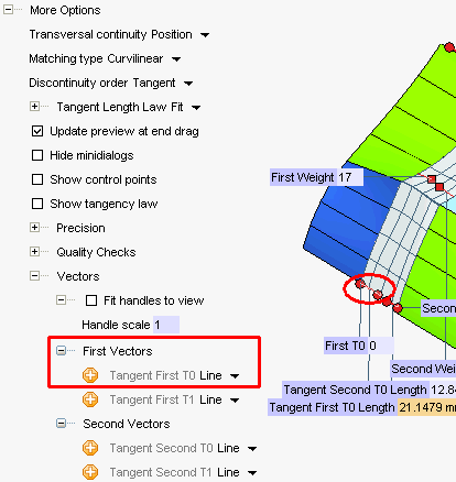
Proper options are available in the Tangent Second T1 node under More Options to control the direction of the tangent vectors in each contour endpoint, as described in " How to define an axis or a line".
In the illustration below, we have set the direction of the tangent vector in the first endpoint of the first contour parallel to the Z axis.


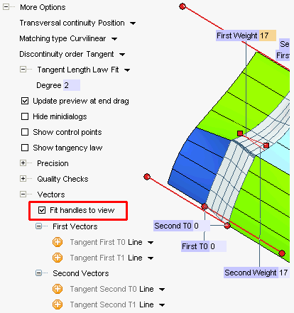
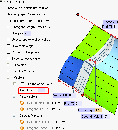
Using the Fit handles to view check box you can control the size of tangent vector handles:
When checked, handles representing tangents and weights are automatically resized so as to fit to the current view size.


When not selected, the handle display size depends on the current Handle scale value.


Defining the alignment of the tangent vectors
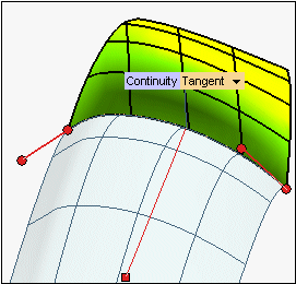
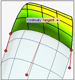
Tangent vectors (either on end points or on additional internal points) are initially perpendicular to the contour.
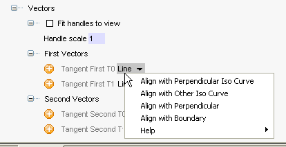
Several options are available to control the alignment of tangent vectors. To access them:
  1. Expand the Vectors node under More Options
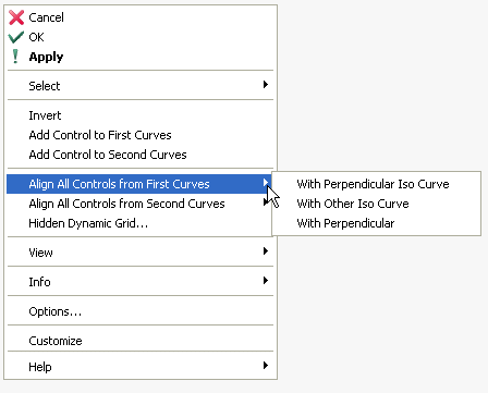
  2. Right-click on the selector corresponding to tangent vector you need to modify the direction of. Choose one of the options in the context menu that shows up.


    • Align with Perpendicular
      The tangent vectors are perpendicular to the contour


    • Align with Perpendicular Iso Curve
      The tangent vectors are oriented along one isoparametric curve of the surface: the one which is closest to the perpendicular direction.


    • Align with Other Iso Curve
      The tangent vectors are oriented along the other isoparametric curve (with respect to the one used in the Align with Perpendicular option)


    • Align with Boundary
      The tangent vectors are oriented along the direction of the border. If there is no border, the option is not available.

Please note that you can also select the same options for all the tangent vectors of a given contour in the global context menu (which shows up if you right-click in the graphics area).


Adding intermediate handles to contours
You can also add handles to any point of each contour, so as to locally control both the weight and the direction. To add a handle to a point of a contour, right-click on the point (if you right-click outside the contour the point will be projected onto it) and select Add Control to First Curves or Add Control to Second Curves, depending on which contour you want to add the handle to.


Length and direction of tangents in the additional points can be managed exactly as in the case of endpoints.


Additional handles can be removed by right-clicking and selecting Remove Control from First Curves / Remove Control from Second Curves.


8 In order to get to know how to control the shape and the smoothness of the resulting blending surfaces, see "Managing contour discontinuities". For example, you might set Matching type under More Options to Ordered discontinuity, so as to establish a correspondence between the discontinuity points on the two contours.


9 Click or to confirm your selections and create the surface.


Click to discard your changes.


Precision
The items available when you expand the Precision node under More Options enable you to define the tolerance values to be used in the computation process.
Position Enables you to set the tolerance value to be used in case of positional continuity, in millimeters or inches, depending on the current unit of measure. It is the difference between the real positional continuity and the one you can obtain.
Tangent Enables you to set the tolerance value to be used in case of tangency continuity, in degrees. It is the difference between the real tangency and the one you can obtain.
Curvature Enables you to set the tolerance value to be used in case of curvature continuity, as a percentage of the maximum curvature.
Degree Enables you to define the tolerance for the degree. It is the difference between the real degree and the one you can obtain for the resulting shape.
Max. No. of Arcs Enables you to define the maximum number of arcs for the resulting shapes.
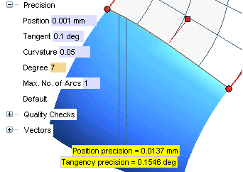
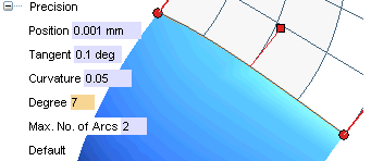
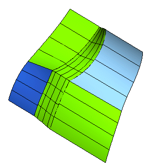
In the following example, the resulting shape is improved by changing the number of arcs.

With just one arc, the required precision values are not reached.
By setting the Max. No. of Arcs to 2, the precision values relative to position, tangency and curvature are smaller then the expected ones.