Managing contour discontinuities
The Blending Shapes command enables you to control the creation of blending surfaces even in the case the selected contours have tangency or curvature discontinuity points (from now on, in this document, we will use "discontinuity" in the sense of "tangency or curvature discontinuity", as positional discontinuities are obviously not allowed).
First of all you will be able to set the discontinuity order to be taken into account, that is to decide whether to consider as "discontinuities" only tangency discontinuities or also curvature discontinuities.
The resulting shape will be composed of as many surfaces as the number of parts into which the selected contours are divided by discontinuity points. You will be able to control continuity — called transversal continuity — along the common borders of the said surfaces.
Furthermore, you'll be able to choose the matching type between the two contours, that is the way to establish the correspondence between them, which heavily affects the final shape of the resulting surfaces.
All of the options mentioned in this document can be found under More Options.
Defining Transversal continuity
First of all you will have to consider transversal continuity, which is continuity between the resulting surfaces along their common borders at the discontinuity points.
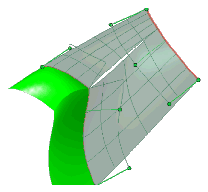
When there is at least one discontinuity in one of the contours, the natural way to build the blending shape would lead to "holes":

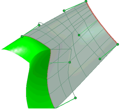
To avoid the creation of holes, change the value of the Transversal continuity drop-down list under More Options from Free to Position, which will apply positional continuity along the common borders at the discontinuity points.

Selecting the Matching type
There can be different ways to establish the correspondence between the two contours, depending on the situations. The Matching type drop-down list enables you to select three different methods to establish the correspondence:
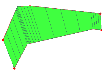
| Curvilinear |
The point on the other contour which corresponds to a discontinuity point is the one that has the same normalized arc length.

|
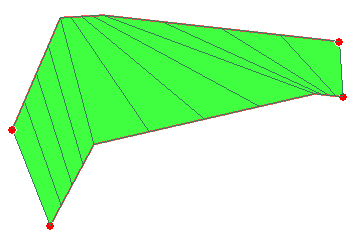
| Ordered discontinuity |
Active only if the two contours have the same number of discontinuity points, this option joins discontinuity points on the two contours according to their order (the first with the first, the second with the second, and so on).

|
Setting the Discontinuity order
The way discontinuities are detected on contours — whether to take into account only tangency discontinuities or also curvature discontinuities — is controlled by the Discontinuity order drop-down list:
| Tangent |
To take into account only tangency discontinuity points. |
| Curvature |
To take into account tangency discontinuity and curvature discontinuity points. |


