Please note that you can accomplish this task by loading file "AdvancedPipe.e3". As you can see, there is a sharp point in the contour to be used as the drive path for the pipe surface.
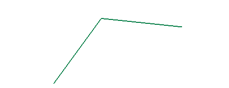
In this task you will use the Pipe Surface command to create a pipe surface along a contour with a sharp point.
Please note that you can accomplish this task by loading file "AdvancedPipe.e3". As you can see, there is a sharp point in the contour to be used as the drive path for the pipe surface.

| 1 | Start the Pipe Surface command. |
|
| 2 | Select the drive curves.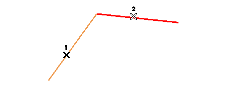 |
|
| 3 | In the Extend/Restrict drop-down list, choose
None, so as not to extend the pipe beyond the drive curves, nor to restrict it. |
|
| 4 | Under More Options, select
With Transitions.
|
|
| 5 | Click the Preview button (  ). ).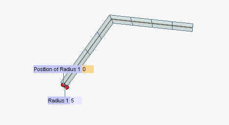 Now you can define the radius of the pipe either by dragging the handle or by specifying the numerical value in the Radius 1 mini-dialog box at a point which is initially the first endpoint of the selected drive curves, but which you can move along such curves either by typing a new parameter value into the Position of Radius 1 box or by interactively dragging the corresponding handle. |
|
| 6 | Change the value of the radius.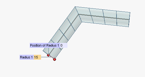 |
|
| 7 | You may want to vary the radius along the path. You can specify different radius values through the Add Radius command of the contextual menu displayed by right-clicking on the point of the drive curves where you want the different radius to be applied (if you don't click exactly on the drive curves, your click point will be projected onto them). A
Radius n and a
Position of Radius n handle/mini-dialog box pair will be displayed each time you do so. In the following illustration, two additional radii have been added, by right-clicking at points 1 and 2 on the drive path.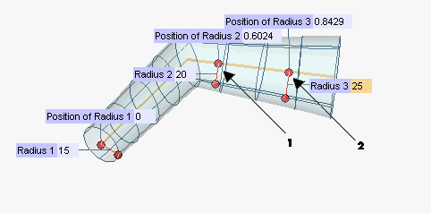 Note that you can move the position of the additional radius by dragging the Position of Radius n handle or by typing a new parameter value in the corresponding mini-dialog box. Additional radii can be removed by right-clicking again and selecting Remove Radius in the context menu:
|
|
| 8 | Click  or or  to confirm your selections and create the pipe surfaces. to confirm your selections and create the pipe surfaces.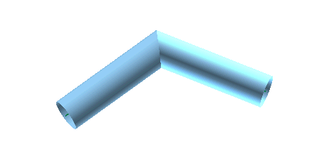 Click  to discard your changes. to discard your changes.Please note that the With Endcaps check box under More Options enables you to create the two surfaces which close the pipe at both of its ends.
|