


Insert Surface
 Fillet
 Spined
The Spined Fillet command enables you to create fillet surfaces between two selected groups of surfaces along a spine curve chain.
The fillet surface will have a circular section if you do not select the two drives. Instead, if you do indicate the drive curve chains — one of which must lie in the first group of surfaces and the other in the second group — the drive curve chains are the loci of the start and end points (u = 0, and u = 1, respectively) of the sections of the fillet surfaces. Along the drives, the fillet surface is tangent to the selected surfaces.
In the Type drop-down list you can select the type of fillet to be created:
| Constant radius | When this type is selected, you will have to specify two groups of surfaces and a spine curve chain. The resulting fillet will have the same radius along the whole spined curve chain. |
| Variable radius | When this type is selected, in addition to the two groups of surfaces and to the spine curve chain, you will also be enabled to specify a Start Radius value and an
End Radius value for the resulting fillet to vary from-to. You can also specify as many
Internal Points as you like, where the radius value can be specified in a specific
Radius mini-dialog box.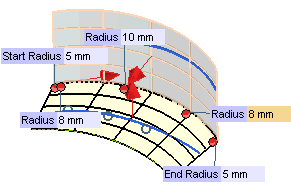 The internal points can also be specified using the snap commands. Furthermore, it is not necessary to indicate them exactly on the spine chain: wherever you specify them, they will be projected onto it. |
| With drives | When this type is selected, no radius is to be specified — as it will automatically be determined by the construction constraints, but two drive curve chains: one on surfaces of Group A (
Drive 1 Curves) and one on surfaces of
Group B (
Drive 2 Curves). The resulting fillet will join the two surfaces through the two drive chains, along which it will also establish tangency continuity. In the following illustration A and B are respectively
Group A and
Group B, 1 and 2 are
Drive 1 Curves and
Drive 2 Curves, while S is the chain of
Spine Curves.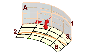 Some notes:
|
The fillet Extension can be chosen among the three available items of the selection list:
| Disabled | Creates a blend surface whose length is only as long as the length at which the two selected surfaces actually intersect.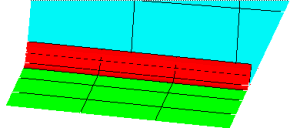 |
| Full | Creates a blend surface whose length extends to the outermost edges of either surface (which ever is longer) at the point where the two surfaces intersect.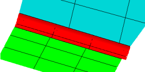 |
| Trimmed | Creates a blend surface whose length at the point where it intersects with the selected surface is extended or trimmed to match the length of the surface at that intersection. If the Automatic cut check box (
Construction -
Advanced category of the
System Options) is selected, the portions of the selected surfaces extending beyond the new blend surface are automatically eliminated.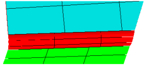 |