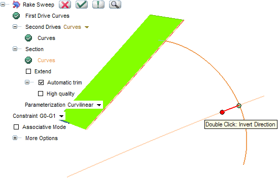
The Rake Sweep command — which simulates the rigid motion of a scraping tool — enables you to create a surface by sweeping one rigid contour — which can be composed of 3D curves (skew) — along two drives, both of which can be contours and fulfilling some contact constraints (it must satisfy the target contact conditions in its initial position). The word contour, in this case, means chain of consecutive curves with the following prerequisites:
- They must have at least internal G0 (positional) continuity.
- The portions of the contours susceptible to be in contact must have at least internal G1 (tangency) or G2 (curvature) continuity according to the requested Constraint cases (see below for details).
But while the first drive must be a contour, the second drive can also be a set of surfaces.
You can proceed as follows.
- First of all select the curves to be used as the first drive (First Drive Curves) and end selection.
- In the Second Drives drop-down list, you can choose:
In this case select
Curves (The selection of surface boundaries and of solid edges is also allowed, provided they fulfill the said conditions).
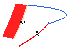
Note that the first drive curves have a particular role: they always drive the motion.
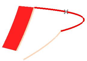
- Select the section curves (Curves under
Section). The section curves must fulfill the requested
Constraint (see below for details) in its starting position.
- The selected section can be extended using the Extend check box:
- When the box is cleared, the section will be used as it is, with no extension.
- When the box is checked, the section will be extended according to the mode you can selected in the adjacent drop-down list (displayed as soon as the box is checked):
| Parameter |
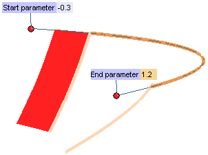
When this mode is selected, you can extend the section at its end points according to its parameterization. Two handles and mini-dialog boxes (Start Parameter,
End Parameter) are displayed, so as to enable you to obtain the extension either by dragging the handle or by typing in the desired value (<0 for the start parameter, >1 for the end parameter).
|
| Tangent |
When this mode is selected, you can extend the section at its end points along the tangent directions. Two handles and mini-dialog boxes are displayed (Length), so as to enable you to obtain the extension either by dragging the handle or by typing in the desired value (>0).
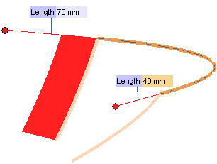
|
| Curvature |
When this mode is selected, you can extend the section at its end points maintaining the curve curvature conditions. Two handles and mini-dialog boxes (Start Parameter,
End Parameter) are displayed, so as to enable you to obtain the extension either by dragging the handle or by typing in the desired value (<0 for the start parameter, >1 for the end parameter).
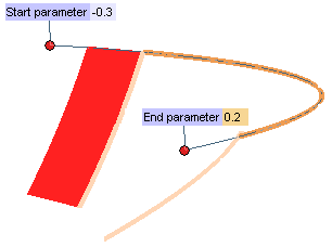
|
- The resulting surface can be trimmed along the drives by using the Automatic trim check box.
- When the box is cleared, the resulting surface is not trimmed.
- When the box is checked, the resulting surface is trimmed along the drive curves. In such case, the High quality check box is displayed:
- When the box is cleared the resulting surface will have internal continuity 2 along both parametric directions.
- When the box is checked, the internal continuity will be G3 (torsion) or G4 (curvature plot curvature).
The Parameterization drop-down list is enabled when only one section group has been selected. You can choose one of the following parameterization types for the section:
| Curvilinear |
the section curves don't need to form a chain. Chains — one or more — are automatically determined by the program. Each chain results in a separate surface. |
| Intrinsic |
the selected curves are not chained. Each curve is swept independently (thus resulting in a separate surface). |
When more than one section groups are selected, the section parameterization is Curvilinear.
- In the Constraint drop-down list you can choose the type of constraint to be applied along the drives:
| G0-G0 |
G0 (positional) continuity will be maintained along both drives. |
| G1-G0 |
G1 (tangency) continuity will be maintained along the first drive, GO continuity will be maintained along the second drive. |
| G0-G1 |
GO continuity will be maintained along the first drive, G1 continuity will be maintained along the second drive. |
Please note that G1-G0 and G0-G1 constraints are not equivalent even switching the drives according to the above note about the particular role of the first drive curves.
Several additional options are available under the More Options node.
- The Mode drop-down list enables you to select the surface construction mode:
| Automatic |
When this item is selected, the construction mode is automatically determined by the program. Specifically:
- When the Constraint is set to G0-G0 or G0-G1, the
Automatic choice is equivalent to setting the
Mode to
Advised and the
Motion Mode to
Along one plane (see below for details).
- When the Constraint is set to G1-G0, the
Automatic choice is equivalent to setting the
Mode to
Advised and the
Motion Mode to
Surface based (see below for details).
|
| Advised |
This mode allows finding a motion in which the section position along the single drive can be precisely defined; the system must follow it as much as possible when satisfying the positional constraint (G0, G1).
When this item is selected, the Motion Mode drop-down list shows up, enabling you to choose the based motion to be used to sweep the contours along the first drive:
| Constant |
The section contour will be swept along the first drive keeping its orientation constant. |
| Constant axis |
The section contour will be swept along the first drive while keeping an axis constant through all the motion. The axis direction can be chosen in the Direction drop-down list. |
| Frenet |
The section contour will be swept along the first drive assuming the orientation of the Frenet reference (tangent, normal, binormal) of the latter. |
| Enhanced Frenet |
The section contour will still be swept along the first drive assuming the orientation of the Frenet reference of the latter as much as possible, with an enhancement enabling the resulting surface to be continuous (G0). |
| Along one plane |
The section contour will be swept along the first drive assuming the orientation of a plane. An Automatic plane check box enables you to control the selection of such plane.
- If the check box is selected, the plane whose orientation will be used to sweep the section contours along the drives is determined automatically as the mean plane of the drive contour. It will obviously be the plane on which the drive contour lies if the latter is planar.
- If the check box is cleared, the plane is to be selected using the Plane normal drop-down list.
|
| Surface based |
The contours will be swept along the first drive keeping an orientation based on the one of the selected surfaces (i.e.: during the motion, the normal will be the one of the surface, while the tangent will be the one of the curve).
New Surface Boundaries can also be selected.
|
Precise definition of the motion for the section and a single drive
When the Advised mode has been selected, for all the motion modes (except
Surface based), it possible to define more precisely the motion (single drive) that the system must follow. You can select a new drive curve (an additional
Drive Curves selector is available in this case in the selection list). The following example shows how selecting an advised drive curve can impact on the final result:
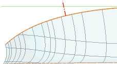 |
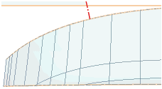 |
| Drive curve not selected |
Drive curve selected (green line of previous image highlighted) |
|
|
| Free |
The sweep motion of the section curves along the drives is a combination of a rotation and of a translation. When the Free item is selected, the
Rotation drop-down list is displayed, enabling you to select the axis of rotation for the rotational component of the sweep motion:
| Free |
The axis of rotation is automatically determined by the program so at to be the best possible. |
| Fixed |
The axis of rotation can be specified by selecting it in the Direction drop-down list (an existing line, a line defined by two points, etc.) |
| Tangent along first drive |
The axis of rotation will be the tangent along the first drive. |
| Normal along first drive |
The axis of rotation will be the normal along the first drive. |
| Binormal along first drive |
The axis of rotation will be the binormal along the first drive. |
| Tangent along section |
The axis of rotation will be the tangent along the section. |
| Normal along section |
The axis of rotation will be the normal along the section. |
| Binormal along section |
The axis of rotation will be the binormal along the section. |
| None |
The rotation component of the sweep motion will be null (the sweep will be just a translation). |
|
-
By specifying a real number varying from 0 to 1 in the Translation vs. rotation box, or by using the adjacent slider, you can indicate how much the rotation and the translation components will affect the sweep motion:
| 1 |
The system will try to generate a motion by using only a translation. Anyway, if a rotation is mandatory (according to the other conditions) it will be taken into account all the same. |
| 0 |
The system will try to generate a motion by using only a rotation. Anyway, if a translation is mandatory (according to the other conditions) it will be taken into account all the same. |
Only in case of the Free mode with
Rotation set to none (no rotation), the system will try to satisfy the constraints only with a translation. The
Translation vs. rotation box is not available in that case. |

|
- The Synchronous drives check box — available for each mode — enables you to control the simultaneity of the motion advancement along the two drives:
- When the box is checked the sweep motion will have the same relative advancement on both drives.
- When the box is cleared, the motion may not have the same relative advancement on both drives.
- The Fixed section adjacent to first drive check box — available only in case of
Free mode and if the section is really perpendicular to the first drive in its initial position — enables you to decide whether the initial contact must be kept along the first drive or not:
- If the box is cleared (see the illustration below (a)), contact along the first drive can change along all of its length
- If the box is checked, (see the illustration below (b)) the resulting surface will keep the same contact to the first drive along all of its length.
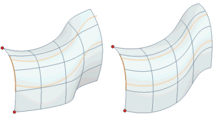
- The Section perpendicular to first drive check box — available only in case of
Free mode — enables you to decide whether the section must be swept perpendicularly to the first drive or not:
- If the box is cleared, perpendicularity along the first drive is not guaranteed.
- If the box is checked, the section will be swept along the first drive so as to be perpendicular to it along all of its length.
- The options under the Discontinuity order enable you ignore the internal discontinuities of the section and/or of the drive contours. However, the motion is not guaranteed (to pass through with the required continuity) as well as the quality of the generated swept surfaces.
| This drive has discontinuous curvature |
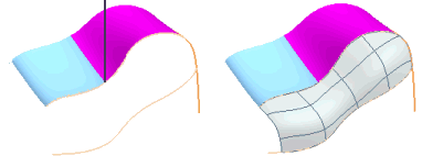 |
The internal section and drives continuity required for the motion depends on the Constraint and options you have selected:
| G0-G0 |
The portion of section and drives susceptible to be in contact should have internal G1 continuity. |
| G1-G0 |
The portion of section and first drive susceptible to be in contact should have internal G2 continuity.
The portion of section and second drive susceptible to be in contact should have internal G1 continuity. |
| G0-G1 |
The portion of section and first drive susceptible to be in contact should have internal G1 continuity.
The portion of section and second drive susceptible to be in contact should have internal G2 continuity. |
| Section perpendicular to first drive |
When this box is checked, the portion of section susceptible to be in contact with first drive should have internal G2 continuity. |
In the First Drive Curves,
Second Drive Curves and
Section curves, you can independently choose different values for the section, the first drive and the second drive.
| Position |
To ignore internal tangency and curvature discontinuities. |
| Tangent |
To ignore internal curvature discontinuities if G1 constraint is requested along one drive. |
| Curvature |
Available only when you have set the Constraint to G1-G0 or G0-G1 or when you have checked the
Section perpendicular to first drive box. |
- The items available when you expand the Precision node enable you to define the tolerance values to be used in the computation process.
| Position |
Enables you to set the tolerance value to be used in case of positional continuity, in millimeters or inches, depending on the current unit of measure. It is the difference between the real positional continuity and the one you can obtain. |
| Tangent |
Enables you to set the tolerance value to be used in case of tangency continuity, in degrees. It is the difference between the real tangency and the one you can obtain. |
| Degree |
Enables you to define the tolerance for the degree. It is the difference between the real degree and the one you can obtain for the resulting shape. |
| Max. No. of Arcs |
Enables you to define the maximum number of arcs for the resulting shapes.
|
| Default |
Sets all the precision values to their default.
|
- The Associative Mode check box enables you to create those associative entities called Skins, that is open solids, which retain a link to the surfaces/curves they derive from (see "
An Overview of Surfaces: Associative Surfaces (Skins)" for further details):
- When the check box is selected, the resulting surface will be a skin. It will retain a link to the entities it derives from. A specific node displaying both the original entities and the resulting skin will be added to the Model Structure.
- When the check box is cleared, the resulting surfaces will not be associative: they will retain no link to the entities they derive from.
Try to ...


 Surface
 Rake Sweep


