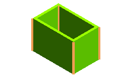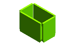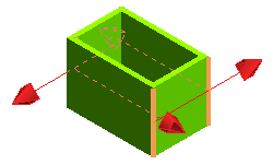

The Edge Rip command enables you to create rips on the selected edges of solid with constant thickness, as shown in the images below.
 |
 |
Proceed as follows to obtain the required results:

 or
or  to confirm your selections to create the rips, as shown in the image below.
 to discard the changes.
| Type | Description | Results in Bottom View |
| Symmetric | the two adjacent parts are cut along the line connecting the inner and the outer edge and placed symmetrically about that line. |  |
| Full | the two adjacent parts are cut along one of their two possible common faces. You can select which of the two by clicking an arrow identifying the cut direction. |  |
| Middle | the two adjacent parts are cut along one of their two possible common faces — you can select which of two the by clicking an arrow identifying the cut direction — and aligned along the middle axis of the selected one. |  |
| Note If the Type you chose is Full or Middle, take a look at the arrows displaying the cut direction and click on them in the case you want to invert it.  |