| 1 |
Open the sample file sib_connecting_rod.e3 which is a static solid model of a connecting rod. This model does not have any history associated with it. Note that you can advantageously use the following procedure on similar static solids, not just in .e3 file format, also in IGES (*.igs or *.iges) and Step (*.stp) file formats. |
| 2 |
Start the Isoparametric Curve Command. Select
V parameter as the
Type and select the
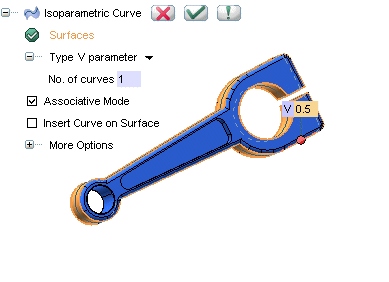
Associative Mode check box. Select all the side faces of the connecting rod, except the inner surface of the small end, shown below:

In this example you may use a V value of 0.5
Note that the inner surface of the small end of the connecting rod is purposefully not selected.
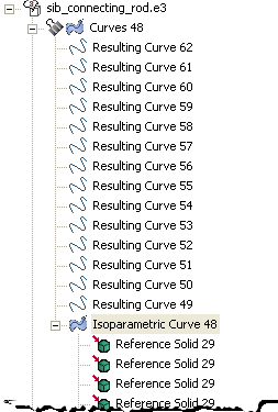
Click  to confirm your selections. A curve surrounding the connecting rod will be created. Note that this curve creates 14 resulting curves as shown in the model structure. to confirm your selections. A curve surrounding the connecting rod will be created. Note that this curve creates 14 resulting curves as shown in the model structure.

|
| 3 |
Start the Parting Plane command. If you have pre selected any curve or the isoparametric curve created in the previous step, reset the your selection (right-click on
Curves from the selection list and select
Reset from the context menu).
Select the Associative Mode check box. Now, right click on the graphic area and select
 and the cursor changes to the following:
Select any one of the 14 curves, created in the second step. The entire siblings of the selected curve (all 14 curves) will be automatically selected. Click  to confirm your selections. to confirm your selections.
The parting plane is created as a skin:

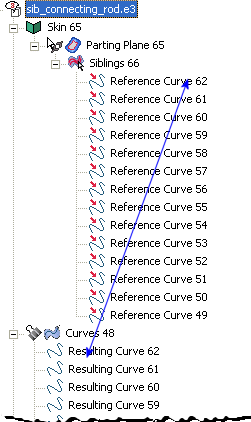
Note that in the model structure, you can find a one-to-one correspondence between the parting plane and the
resulting curves of the isoparametric curve. This is due to the fact that the siblings selection that we employed picked up all siblings of the parent event, i.e; the isoparametric curve.

|
We have purposefully avoided the inner surface of the small end of the connecting rod in the step 2. Suppose that we want the parting plane on that surface as well. Since we have employed siblings selection for creating the parting plane, all we have to do is:

 to confirm your selections. A curve surrounding the connecting rod will be created. Note that this curve creates 14 resulting curves as shown in the model structure.

 Siblings and the cursor changes to the following:
  to confirm your selections.


