Automatic Dimensioning of Electrode from the Work Plane origin
The dimensioning of the electrode with respect to the work plane origin helps in easy manufacturing of the electrode. In the following tutorial you will create an electrode using the Mold Electrode command. Also you will automatically generate the dimensions between the reference point in the electrode and the Work Plane origin. Open the electrode.e3 file available in the Samples/mold folder present at the installation location and follow the steps given below.
- Move the Work Plane away from the electrode along the X axis by 200mm using the command as shown in the image below. This will help in better understanding of the electrode dimensioning.
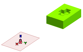
- Follow the steps from 1 to 6 of the Creating the Electrode tutorial.
- Under the Head Shape node, select the Show all reference points check box and view all the reference point of the electrode head as shown in the image below.
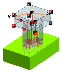
- Double click on a reference point as highlighted (point in Green) in the above image. A datum point is created at this point.
- Click
 or
or  to confirm your selections. A message dialog box appears as shown in the image below.
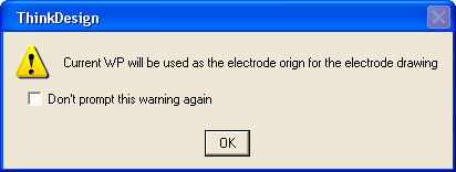
Click OK.
- The electrode file is created at the location of the previously opened file. For this tutorial it will be in the Samples\mold folder with file name as electrode_1.e3.
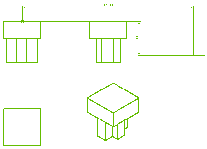
- Open the electrode_1.e3 file and create a drawing from the current model using the command. The different view of the electrode is as shown in the image below.
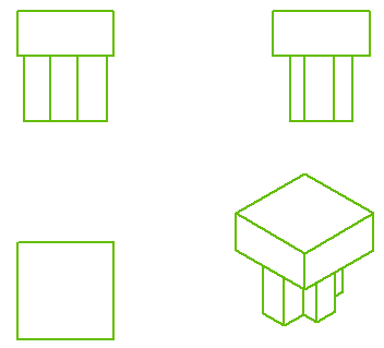
- Right-click on the Graphics Area and select the options. In the Document Properties tab, select the Enable for electrode origin check box from the Drawing-Dimensions category and enter 30 in the Axis length text box.
- Right-click on any of the view and select the option in the context menu. The dimensioning for the selected view is calculated with respect to the Work Plane and displayed as shown in the image below.


 or
or  to confirm your selections. A message dialog box appears as shown in the image below.


 or
or  to confirm your selections. A message dialog box appears as shown in the image below.

