
![]()
Insert MoldDesignStandard Parts
The Mold Standard Parts command enables you to insert standard parts available in the installation. The standard parts such as Ejector Pin, Core Pin, Sprue Bush and Screws can be inserted into the mold base.
| Note The standard parts can also be inserted from the thinkparts catalog. |
On starting the command select the points for the Positioning Points selector which define the location for inserting the standard parts in the mold base. The head of the standard part will be positioned at the selected point. You can select not only snapped points but also free points on the Work Plane. The graphical feedbacks are different: each snap point is displayed using a red ball, each free point is displayed using a grey cross marker.
This capability enables you to position the standard part in any point (free positioning) and then, by clicking on its anchor point, to move it specifying the X and Y values or by dragging it. The coordinate mini-dialog boxes are available only if you select one standard part. In the other case (snap) you can change the positioning point to free by double clicking the anchor point or selecting it and use the Unlink command in the context menu.
After the selection of a positioning points, you can easily add to this selector other points by using the following context menu items:
Transform Mirror about X axis Mirror about X axis
|
It enables you to add the mirrored points about X of the Work Plane. |
| TransformMirror about Y axis
|
It enables you to add the mirrored points about y of the Work Plane. |
| TransformCopy along X direction
|
Through the Copy of points dialog box, you are enabled to add a specific number of points along the X axis at a defined Step Distance |
| TransformCopy along Y direction
|
Through the Copy of points dialog box, you are enabled to add a specific number of points along the Y axis at a defined Step Distance. |
| TransformReset Marker Selection |
It enables you to reset the marker selection. For deselecting only one point, you have to click on it by pressing <CTRL>. |
This option enables you to position the standard parts in symmetric points along X or Y or create a pattern of standard parts along X or Y.
| Ejector pin | It is a long pin that extends and pulls back to force the molded part out of the cavity. |  |
| Core pin | It is used as core inserts in situations where a hole is required to be formed on the mold component. |  |
| Sprue bush | It is used to transfer the plastic material from the injection machine to the cavity. See also the Note below. |  |
| Screw | It acts as fasteners to the plates in the assembly. See also the Note below. |  |
| Customize | It integrates the customized catalog into the command. |
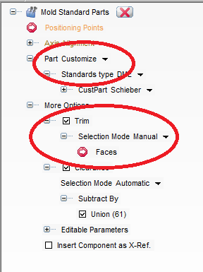
The list of installed catalogs can be selected in the Standards type drop-down list. On selecting a catalog, a node is displayed with the name of the standard part under the Standards type drop-down list. On expanding the node a part catalog is displayed. It contains a part list with the standard specification. You can select the part from the catalog.
Under More Options there are three options available for selection.
The Trim option is available also for custom parts. The behavior of trim for custom part is the same as trim for ejector and core pin.
When the Trim check box is selected, the standard parts are trimmed either manually or automatically in the mold base. There are two options available in the Selection Mode drop-down list.
· Automatic: When selected, the standard parts are trimmed up to the cavity surfaces in the mold base.
· Manual: When selected, the standard parts are trimmed up to the selected face/s. The face is selected using the Faces selector.
Please note that when a new standard part is inserted on an already existing standard part (including custom parts) and using the automatic selection, clearance should not be created. To achieve clearance on any standard part, manual selection must be used.
See the images below.
· When Trim is selected and the selection mode is Automatic.

· When Trim is selected and the selection mode is Manual.
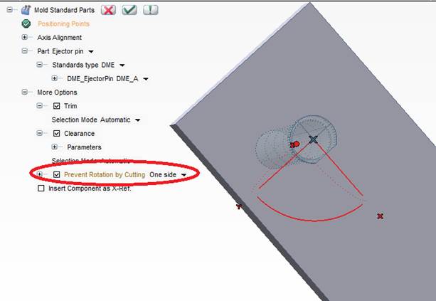
· When the Prevent Rotation by cutting check box is selected and the value is One side, the inserted part is prevented from rotating by forming a one side non circular head preview.
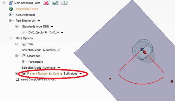
· When the Prevent Rotation by cutting check box is selected and the value is Both sides, the inserted part is prevented from rotating by forming a two sides non circular head preview.
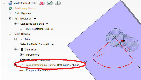
· When Prevent Rotation by cutting is selected and the value is Both sides - oblong, the inserted part is prevented from rotating by forming a two side oblong head preview.
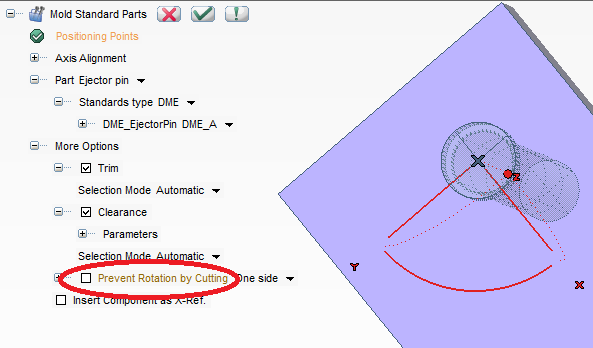
· When Prevent Rotation by cutting is not selected, the inserted part is allowed to freely rotate by forming a circular head preview.
When the standard parts are redefined, then options like Part, Trim, Clearance and Prevent Rotation by Cutting, Insert Component as X-Ref. are not available for selection in the selection list.
When there is more occurrences of the same standard parts — same name in the Model Structure — in order to change one of them separately, it is mandatory to use the Move to New Standard Part Group command which removes the selected component from the grouping and creates another occurrence with a different name, in order to allow editing.
Also, you can delete individual standard parts from the mold by right-clicking on the standard part component in the Model Structure and selecting Delete from the context menu.
Finally, You can insert a new mold catalog and custom part catalog by editing the index of suppliers in the files\MoldDesignData\StdPartCatalogIndexMap.xml file in your installation.