Managing the Section Planes
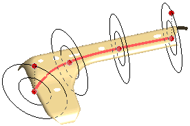
During the application of the GSM Spined Twist command, multiple section planes are generated over the part to define the twist. The section planes are of circular form and their limits are defined by the Max. radius (outside radius) and Min. radius (inside radius) values.

By default, the preview of the section planes are not displayed. The preview needs to be activated by selecting the Show preview check box in the Advanced Options dialog box. In this dialog box, you can also do the global settings to define the section plane size and their number of instances to be present on the spine curve.
Note
The twisting action of the GSM Spined Twist command is applied in the zone lying in-between the section plane limits. In the zone outside Max. radius and inside Min. radius, the standard GSM modifications are applied to modify the surface in an even manner. |
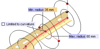
It is also possible to individually define the section plane limits by editing them explicitly. To do so, right-click at the section plane handle (red dot on the spine curve) and select Show Section Options from the context menu. The radius values of that section plane are now editable.

You can use the mini-dialog boxes to specify the radius values or drag the respective handles to modify them dynamically. The Max. radius value (in the mini-dialog box) can range between the specified Min. radius (in the mini-dialog box) and Max. radius set in the Advanced Options dialog box. The Min. radius value can range between 0 and Max. radius.
By default all the section planes are placed equidistant from each other. However, they can be individually moved to the required location just by dragging the section plane handle.
Related topic

