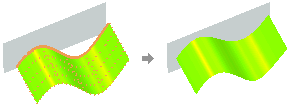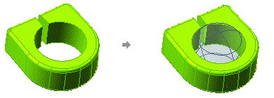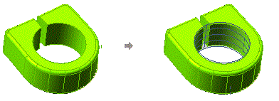


The Advanced GSM and Zone Modeling commands enable you to specify shape constraints on curves and points. This results in matching the selected curve/point with a target shape. To apply these constraints, you have to use the Target Shape drop-down list under the Target Shape node.
Shape constraint on a curve
For selecting the curves to apply shape constraint, select Curves in the Target Shape drop-down list. Now the Curves selector is displayed, with which you can make the curve selection.
Shape constraint on a point
For selecting the points to apply shape constraint, select Points in the Target Shape drop-down list. Now the Group 1 node is displayed. In the corresponding drop-down list you can select the following options to define the point selection mode.
| Standalone | Select free points with the Points selector. |
| Points on surface | Select points (Points) lying on a surface (Support Surface). |
| Points on curve | Select points lying on a curve with the Points selector. |
| ASCII File | Point coordinates to be read from an ASCII file to be selected. (For details see "Reading point constraints from an ASCII file".) |
Note that you can select points in multiple groups, and define the shape constraint explicitly for each group.
Once the curve/point selection has been done, the Constraint mini-dialog box is displayed on the curve/point in the Graphics Area and you can select one of the following constraints to be applied from the corresponding drop-down list. Depending upon the selected option, additional options will be displayed to make the necessary selections.
| Keep plane | The selected boundaries are preserved on the plane on which they lie. |
| Keep plane + make symmetric | The selected boundaries are mapped to a user defined plane while maintaining G2 continuity along the boundary. Hence, the resulting surface and its mirrored copy with respect to the plane will be G2 continuous. |
| Target Line | The selected boundaries are mapped to a user defined line. Target line has to be selected with the Reference Line selector. |
 |
|
| Target Plane | The selected boundaries are mapped to a user defined plane. The target plane has to be selected with the Reference Plane selector. |
| Target plane + symmetry | The selected boundaries are mapped to a user defined plane while maintaining G2 continuity along the boundary. Hence, the resulting surface and its mirrored copy with respect to the plane will be G2 continuous. The target plane has to be selected with the Reference Plane selector. |
| Match Plane | The selected boundaries are mapped to a automatic or partially computed plane. See Remark section for more details. |
 |
|
| Target Sphere | The selected boundaries are mapped to a user defined sphere. Target Sphere has to be selected using the Center and Radius selectors. |
| Match Sphere | The selected boundaries are mapped to a automatic or partially computed sphere. See Remark section for more details. |
 |
|
| Target Cylinder | The selected boundaries are mapped to a user defined cylinder. Target cylinder has to be selected using the Origin, Direction and Radius selectors. |
| Match Cylinder | The selected boundaries are mapped to a automatic or partially computed cylinder. See Remark section for more details. |
 |
|
| Target Circle | The selected boundaries are mapped to a user defined circle. Target circle has to be selected using the Center, Direction and Radius selectors. |
| Match Circle | The selected boundaries are mapped to a automatic or partially computed circle. See Remark section for more details. |
| Rigid Motion | The selected boundaries are transformed in order to preserve the Euclidean distance between every pair of initial/target. |
| Target Surface | The selected boundaries are mapped to a user defined surface. Target Surface has to be selected using the Reference Surface selectors. |
 |
When you select as constraints Match Plane, Match Sphere, Match Cylinder, Match Circle, a new drop-down list appears under the Curves/Points selector. This drop-down list allows to select already known shape data for shape computaion.
In Automatic case, the characteristics of the surfaces are internally computed and not defined by the user.
For others cases, depending upon the selected option, additional options will be displayed to make the necessary selections.