| 1 |
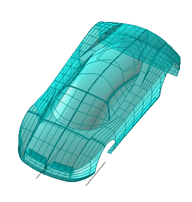
Make sure the Entities drop-down list (under Entities to Be Modified) is set to Solid (and if it isn't, select the Solid item).
To create a solid which will retain an associativity link to its base entities, so that if you modify such entities the solid will be updated accordingly, select the Associative Mode check box.
|
| 2 |
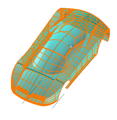
Select the solid to be modified.
 |
| 3 |
Make sure the Perpendicular drop-down list under More Options is set to Axis of revolution. If it is not, select the Axis of revolution. For a detailed description of the two available methods, we strongly recommend that you read "Using the GSM Radial Bend command and its different methods". |
| 4 |
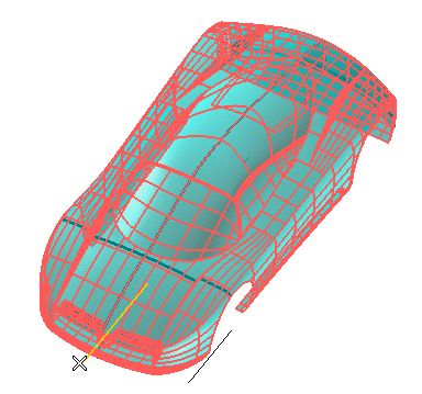
In the Axis of revolution drop-down list, select Line. Then click on the axis shown in the following illustration:
|
| 5 |
In the Bend line drop-down list, choose Line. Select the line which defines the radial bending direction.
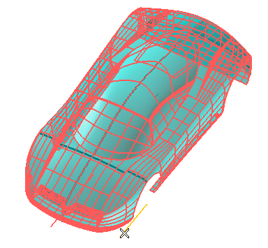
Three handles are displayed:
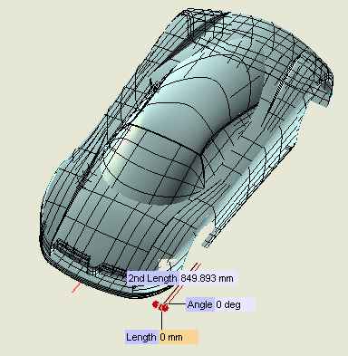
- The one corresponding to 2nd Length enables you to modify the length of the bending line
- The ones corresponding to Angle and Length enable you to perform the bending in a polar reference system with its origin in the endpoint of the bending line.
|
| 6 |
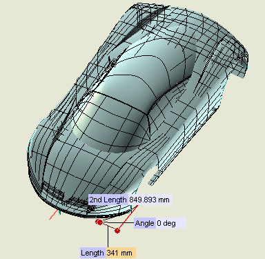
Drag the Length handle to the new position you want, or set the Length value.
|
| 7 |
Click  or or  to confirm your selections modify the shape of the object. to confirm your selections modify the shape of the object.
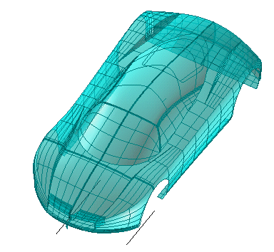
Click  to discard your changes. to discard your changes. |


 or
or  to confirm your selections modify the shape of the object.

 to discard your changes.