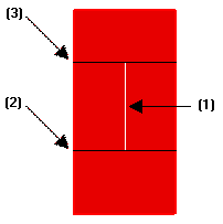
(1) — the line used as a reference
(2) — the First cutting line
(3) — the Second cutting line.
When modeling an object, the line you select as a reference also defines the portion of the object which the controlled modification will be applied to. One or two "cutting lines" are thus identified passing through the reference line end points.
 (1) — the line used as a reference (2) — the First cutting line (3) — the Second cutting line. |
Constraining conditions to be applied along each of the two cutting lines can be selected under More Options respectively in the First and in the Second drop-down lists.
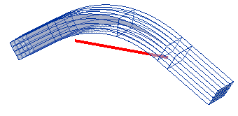
In the following example ("bend_constraints.e3"; the line of bend is the red one, while the cutting lines are vertical lines through the endpoints of the line of bend) you will find some noticeable situations. Please note that the example refers to the GSM Bend command, but the same concepts apply also to the GSM Twist and GSM Radial Bend commands. The following illustrations show different settings and the corresponding results:
The unmodified part (i.e: the one outside the influence of the bending line) is moved so that it will ensure positional continuity. |
The unmodified part (i.e: the one outside the influence of the bending line) is moved so that it will ensure positional continuity. |
which you can appreciate in a 3D view: 
|