using the two modes available in the Perpendicular drop-down list under More Options:
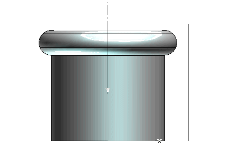
In the following step-by-step example you will use the GSM Radial Bend command to modify the shape of the solid contained in file "GRB_Sample_TwoModes.e3" and shown in the illustration below:

using the two modes available in the Perpendicular drop-down list under More Options:
| 1 | Make sure the Perpendicular drop-down list under More Options is set to Axis of revolution. If it is not, select Axis of revolution. |
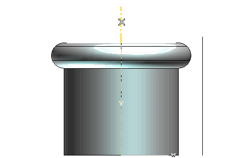
| 2 | In the Axis of revolution drop-down list, select Line. Then click on the axis shown in the following illustration:
|
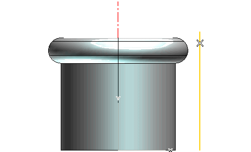
| 3 | In the Bend line drop-down list, choose Line. Select the line which defines the radial bending direction.
|
| 4 | Make sure the Entities drop-down list (under Entities to Be Modified) is set to Solid (and if it isn't, select the Solid item). To create a solid which will retain an associativity link to its base entities, so that if you modify such entities the solid will be updated accordingly, select the Associative Mode check box. |
| 5 | Select the solid. Three handles are displayed:
|
| 6 | Drag the Length handle to the new position you want, or set the Length value. Repeat the operation with different values to appreciate the change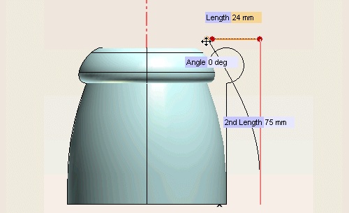 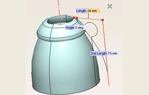
|
| 7 | Now drag the 2nd Length handle or set the 2nd Length value.
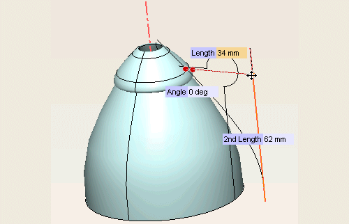 Finally, change the Length value again to obtain the following shape. 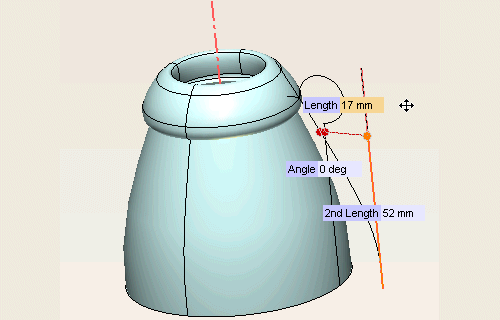
|
| 8 | Now, change the mode. In the Perpendicular drop-down list under More Options select Bend line.
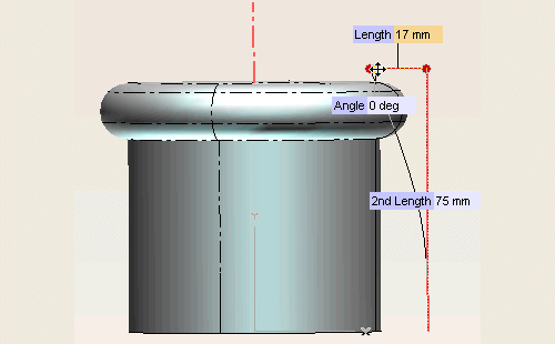
|
| 9 | Try now to appreciate the change when you modify the Angle.
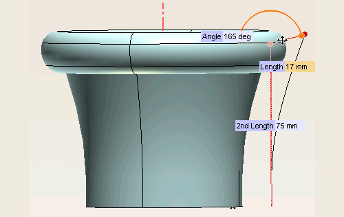
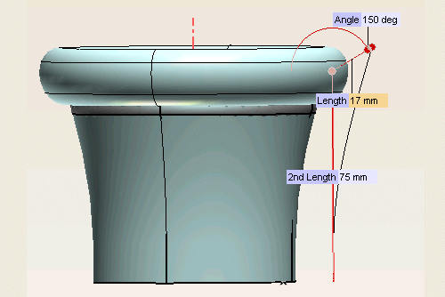
|
| 10 | Under More Options, First, change the Status to Rotation and see what happens (the side profile is much more like a straight line than when the Status was set to Fixed. See "Constraints along the first cutting line" for further details).
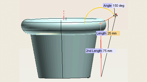
|
| 11 | Now, suppose you set the Perpendicular drop-down list to Axis of revolution again and leave the Status under More Options, First, set to Rotation
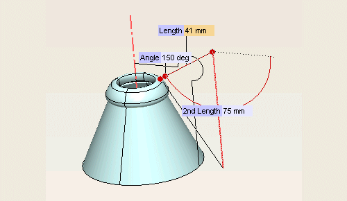
|