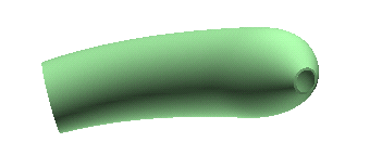
by using the GSM Radial Bend command, so that the solid will change as follows:
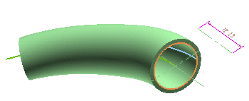
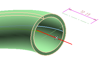
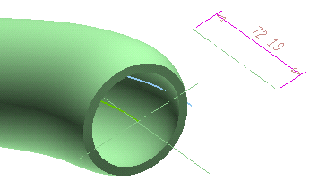
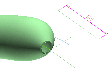
In the following step-by-step example you will modify the shape of the solid contained in file "GRB_Sample.e3" and shown in the illustration below:
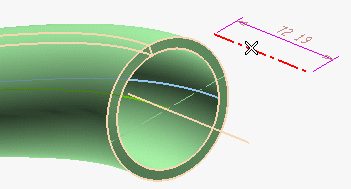
by using the GSM Radial Bend command, so that the solid will change as follows:
To begin with, open file "GRB_Sample.e3" and start the GSM Radial Bend command. If not already set, change the display mode to Shaded View Boundaries and Hidden Lines.
| 1 | Make sure the Entities drop-down list (under Entities to Be Modified) is set to Solid (and if it isn't, select the Solid item). To create a solid which will retain an associativity link to its base entities, so that if you modify such entities the solid will be updated accordingly, select the Associative Mode check box. |
|
| 2 | Select the solid you want to modify.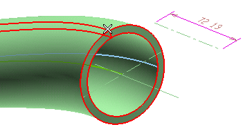 |
|
| 3 | Make sure the Perpendicular drop-down list under More Options is set to Axis of revolution. If it is not, select the Axis of revolution. For a detailed description of the two available methods, we strongly recommend that you read "Using the GSM Radial Bend command and its different methods". | |
| 4 | In the Axis of revolution drop-down list, select Line. Then click on the axis shown in the following illustration:
|
|
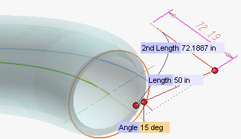
| 5 | In the Bend line drop-down list, choose Line. Select the line which defines the radial bending direction.
 Three handles are displayed: 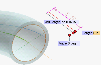
|
|
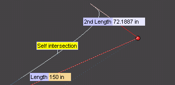
| 6 | Drag the Length handle to the new position you want, or set the Length value.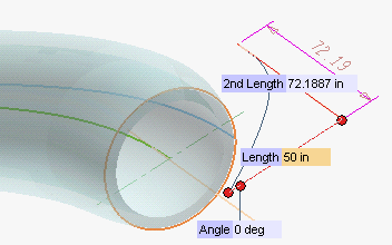
|
|
| 7 | Drag the Angle handle or set the Angle value.
|
|
| 8 | Click  or or  to confirm your selections modify the shape of the object. to confirm your selections modify the shape of the object.
 Click  to discard your changes. to discard your changes. |
Applying the changes to the original entities or to copies
Hiding the original entities when using the command While you are using the command, you can select the Hide check box to temporarily hide the original entities, in order to better appreciate the changes you are making. The entities will be hidden only as long as the command is being executed. |
To obtain the result shown at the beginning of this article, you can double-click on the driving dimension associated with the line used as the bend line, to start the Modify Driving Dimension command and type in the new value. After rebuilding, you'll get the shown result.
 ), the corresponding warning will also be displayed: